1250 Frequency Response Analyzer Installation
CWB / 1250_Op / Issue 9A 2-11
6. Finally, fit the 1250 into the rack, as follows:
a. Offer the 1250 up to the rack and feed the inner telescopic slide members into the
outer members, pushing the unit into the rack until the locking catches engage
and lock.
b. Depress both catches and push the unit fully into the rack, ensuring that no cables
are trapped.
c. Tighten the screws on the outer slide members in the following order:
1. The M5 screws securing the rear bracket to the rack.
2. The M5 screws securing the front bracket to the rack.
3. The 8-32 UNC screws securing the rear bracket to the outer slide member.
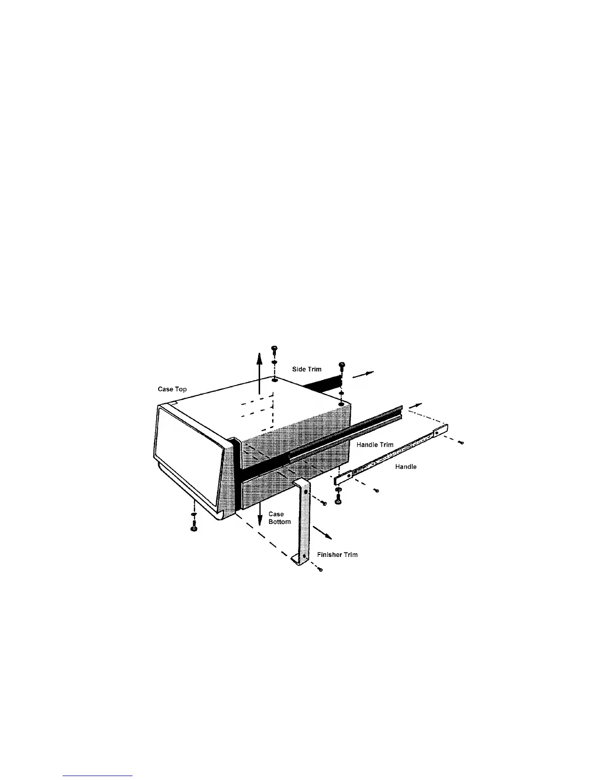
2.5.4 FITTING TELESCOPIC SLIDE MOUNTING KIT 12505C (JONATHAN)
Remove the following items from the unit. as shown in Fig. 2.9:
a. Finisher Trim (two off)
Retain the four M4X16 panhead screws and M4 crinkle washers for securing the
rack ears.
b. Handle and Handle Trim
Figure 2.9 - Removal of trims, handle, top and bottom cases