EasyManua.ls Logo

Solartron 1250 - Data Flow Schematic

Default Icon
195 pages
Print Icon
To Next Page IconTo Next Page
To Previous Page IconTo Previous Page
Loading...
Facilities For More Complex Measurements 1250 Frequency Response Analyzer
10-8 CHFR/1250/1
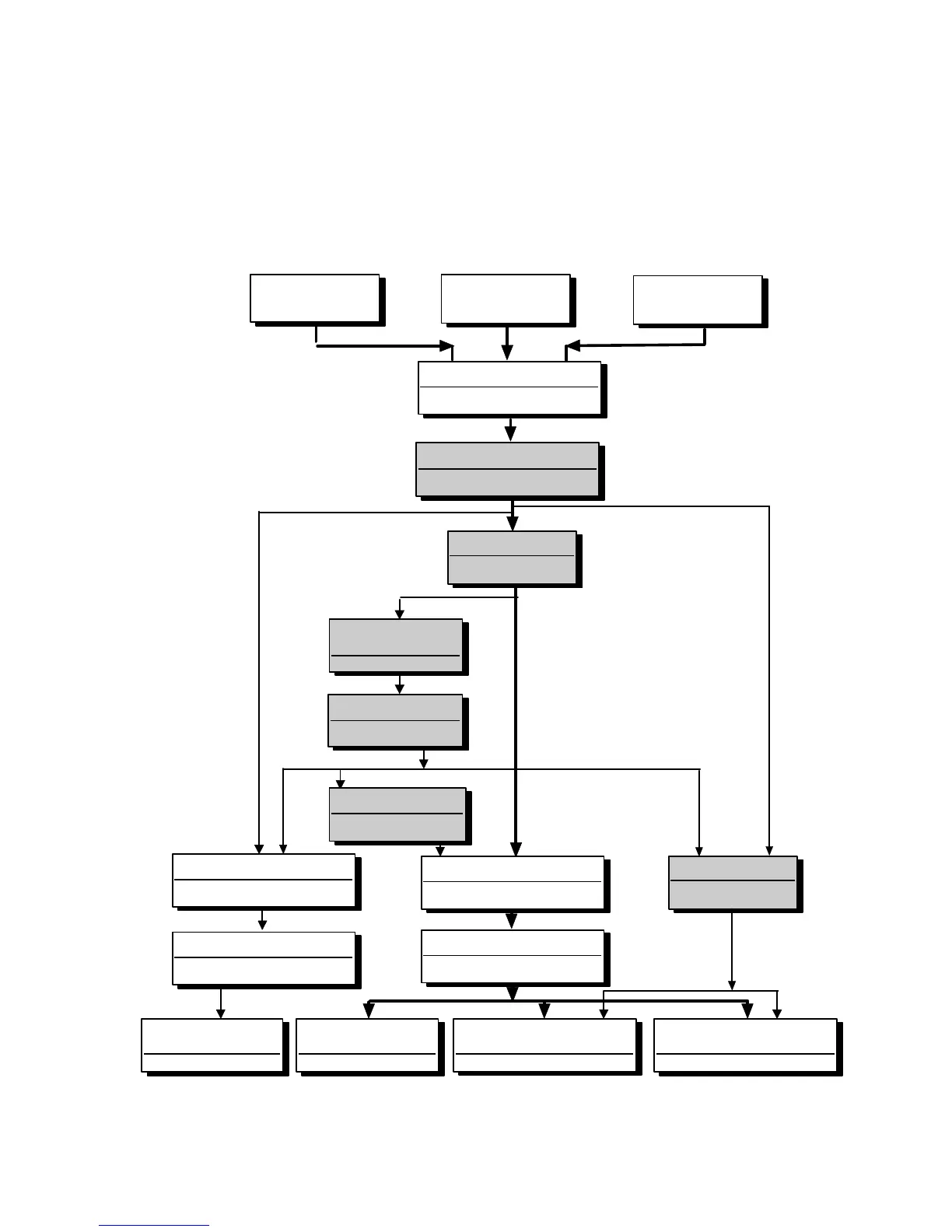
10.2 DATA FLOW SCHEMATIC
Each stage is represented by a box. Where the box has two sections, the upper
contains the title of the facility and the lower shows the relevant Front Panel key.
Boxes shown shaded, such as LIMIT CHECK, are optional facilities which may be
placed in the data path by the relevant key. If not switched in, they have no effect on
the data.
The main data path is shown in heavy line.
ANALYZER 1 ANALYZER 2
OTHER
ANALYZERS
DISPLAY SOURCE
DISPLAY / PLOTTER MENU
xω
n
and SCALE
FUNCTION
LIMIT CHECK 1
FUNCTION
FILE
OFF/ALL/FAIL/PASS
DATA OUTPUT
FILE OUTPUT
VIEW FILE
LIMIT CHECK 2
PLOTTER X ITEM & Y ITEM
DISPLAY / PLOTTER MENU
ANGLE CONVENTION
FUNCTION
ANGLE CONVENTION
FUNCTION
CO-ORDINATE SELECTION
DISPLAY / PLOTTER MENU
RS423
OFF/ALL/FAIL/PASS/DUMP
DATA OUTPUT
GPIB
OFF/ALL/FAIL/PASS/DUMP
DATA OUTPUT
PLOTTER
INTERFACE/GPIB
DISPLAY/PLOTTER
DISPLAY
OFF/ALL/PASS/DUMP
DATA OUTPUT
LIMIT CHECK 1
FUNCTION

Table of Contents

Related product manuals