Frequency Response Analyzer Additional Generator Controls
AMK/1250/2 9-5
9.2 AMPLITUDE COMPRESSION
9.2.1 INTRODUCTION
It is sometimes desirable to control the amplitude of the signal at an intermediate point
in the measuring circuit, rather than at the Generator output. For example, the input to
an amplifier may need to be kept within close limits either side of the nominal value, to
avoid non-linear operation. With Amplitude Compression, the Generator output is
varied automatically to satisfy this condition, by using one of the Analyzer Channels as
part of a feedback control loop.
A safety feature is included in the control loop which limits the Generator output
amplitude to a 'safe' level selected by the user; this is explained in Section 2.3.
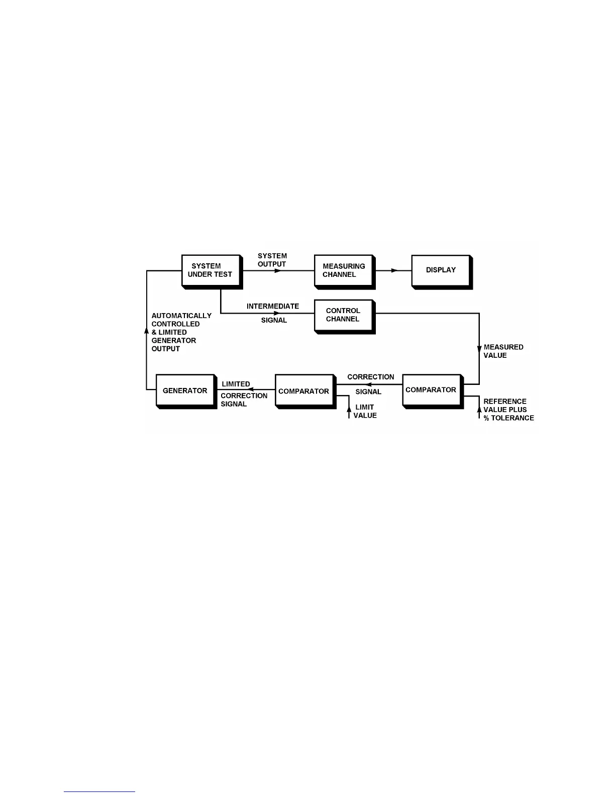
Fig. 9.4 shows the Amplitude Compression facility schematically.
Figure 9.4 - Amplitude Compression Schematic.
9.2.2 PRINCIPLE OF OPERATION
In the arrangement shown in Fig. 9.4, an intermediate signal is monitored at some point
within the system under test. The user defines the nominal voltage which is to be
maintained at this point and the percentage error that can be tolerated. For example, if
1 volt ± 25% is specified, the 1250 will attempt to hold the monitored voltage between
the levels 0.75 and 1.25 volts.
One of the Analyzer Channels is connected to the monitored point to form part of the
control circuit. The other Analyzer measures the output of the system under test. Both
Analyzers measure their respective signals simultaneously.
The Display is shown using the measuring Channel as its source, but it can use either or
both, as explained in Chapter 7.
If the Intermediate Signal is outside the tolerance band during a measurement, the 1250
does not display the invalid reading but attempts to correct the Generator output
appropriately before making a second measurement. The resulting reading is displayed,
valid or not, but "Error 84" is indicated with the reading if it is still invalid.