Making Measurements: The Analyzers 1250 Frequency Response Analyzer
5-2 AMK/1250/3
5.1 INTRODUCTION
Having completed the Generator Menu, the Analyzers may now be set up. Channels 1
and 2 are connected to Analyzers 1 and 2 respectively. The numbering of any
additional Analyzers is explained in Chapter 16, The 1251 Multichannel Analyzer
System.
5.2 SETTING THE [ANALYZER COMMON] MENU
Press ANALYZER MENU. The Display will show [ANALYZER COMMON]. The term
'COMMON' indicates that the values entered here will apply to all the Analyzers in the
system. Five soft keys are assigned as described below.
5.2.1 ∫∫ TIME (where ∫ is the symbol for integration).
Enter the required numerical value here, plus the chosen units, i. e. time [sec] or cycles
[cyc]. If the signal to be analysed is noisy, the rms error in the readings due to the noise
tends to zero as the integration time is increased. Hence the longer the integration time
that can be tolerated, the closer the final reading will approach to the true value of the
wanted signal.
The integration time chosen usually has to be a compromise between speed of
measurement and acceptably small errors in the reading.
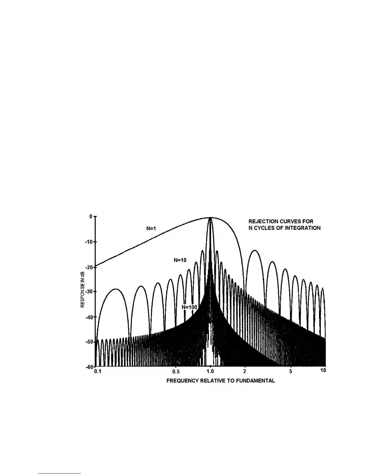
The ability of the Analyzers to reject unwanted frequencies, especially harmonics is
illustrated in Fig. 5.1
Figure 5.1
The curves indicate that one cycle of integration will give a reasonable reading where
the signal contains little random noise, but may have some harmonic distortion.