Options 1250 Frequency Response Analyzer
15-14 AMK/1250/2
15.3.3 PRESET CONTROLS
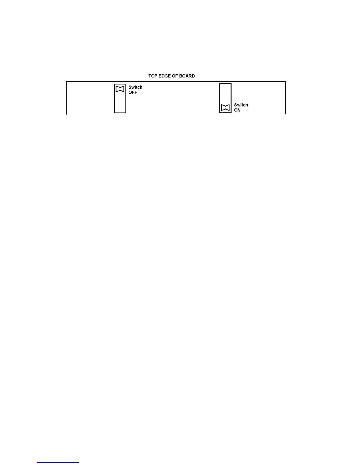
12503 carries two sets of 4 switches, close to the top edge, which may be accessed
when the board is in the frame. The 'on' and 'off' positions of the switches are as shown:
Fig. 15.6 - Module 12503 switch positions
a. Point Mode. Set switches SlA and SIB as shown for the different plotter speeds:
Plotter Speed
> 150cm/s >100cm/s >80cm/s >30cm/s
SIA on on off off
SIB off on off on
b. Vector Mode. Set switches SIC and SlD as shown for the different plotter
accelerations:
Plotter Acceleration
> 5000cm/s
2
> 2000cm/s
2
> 1000cm/s
2
> 500cm/s
2
SIC on off on off
SID off off on on
c. Pen Up/Down Delay. Set switches S2C and S2D as shown for the different plotter
pen delays:
Delay
< 40ms < 70ms < 170ms < 300ms
S2C on off on off
S2D off off on on
d. Pen Down Actuation.
If the plotter requires contact closure to give Pen Down, use pins 24 and 25 on
Interface A connector.
If the plotter requires a line to be grounded to give Pen Down, set S2B to 'on' and use
only pin 25 on Interface A connector.
15.3.4 SETTING UP AND PERFORMING A PLOT
The procedures to be followed are as given in Chapter 12, Section 4.2 onwards.