Frequency Response Analyzer Additional Generator Controls
AMK/1250/2 9-3
The other four keys control the rate at which the frequency is altered. They are graded
from "SLOW" through to "FAST" and respectively change the frequency in larger and
larger increments. These keys may be either pressed and released successively, in
which case the frequency will alter by one increment per press, or a key may be held in,
in which case the frequency will keep changing by the relevant increment until the
maximum or minimum value is reached, depending upon direction of change.
A warning "beep" indicates that the limit has been reached, and ERROR 43 will be
displayed briefly. As the FAST (coarse) key changes the frequency in relatively large
increments. a maximum or minimum limit will be reached which is inside the 1250's
capabilities. However, by then operating the slower (fine control) keys, the absolute
frequency limits can be obtained.
Note 1. The frequency shown here as "x.xxxx" is the last frequency entered. This will
be zero if the 1250 has just been initialised. To enter a new initial frequency upon which
the VARIABLE controls can operate, use the Generator Menu keys as described in
Chapter 4.
Note2. When "varying" frequency, the increments are linear below 1.0 Hz then
logarithmic from 1 Hz upwards.
Varying the Amplitude and Bias. These can be varied in a similar manner to that
described above for "Frequency".
Amplitude increments are linear from 0 to 1.0 V rms, then logarithmic thereafter.
Bias can go below 0 V, i.e. negative. The increments are linear between -1.0 V and
+1.0 V but logarithmic outside these values.
9.1.4 METHOD 2, WITH ANALYZERS RUNNING
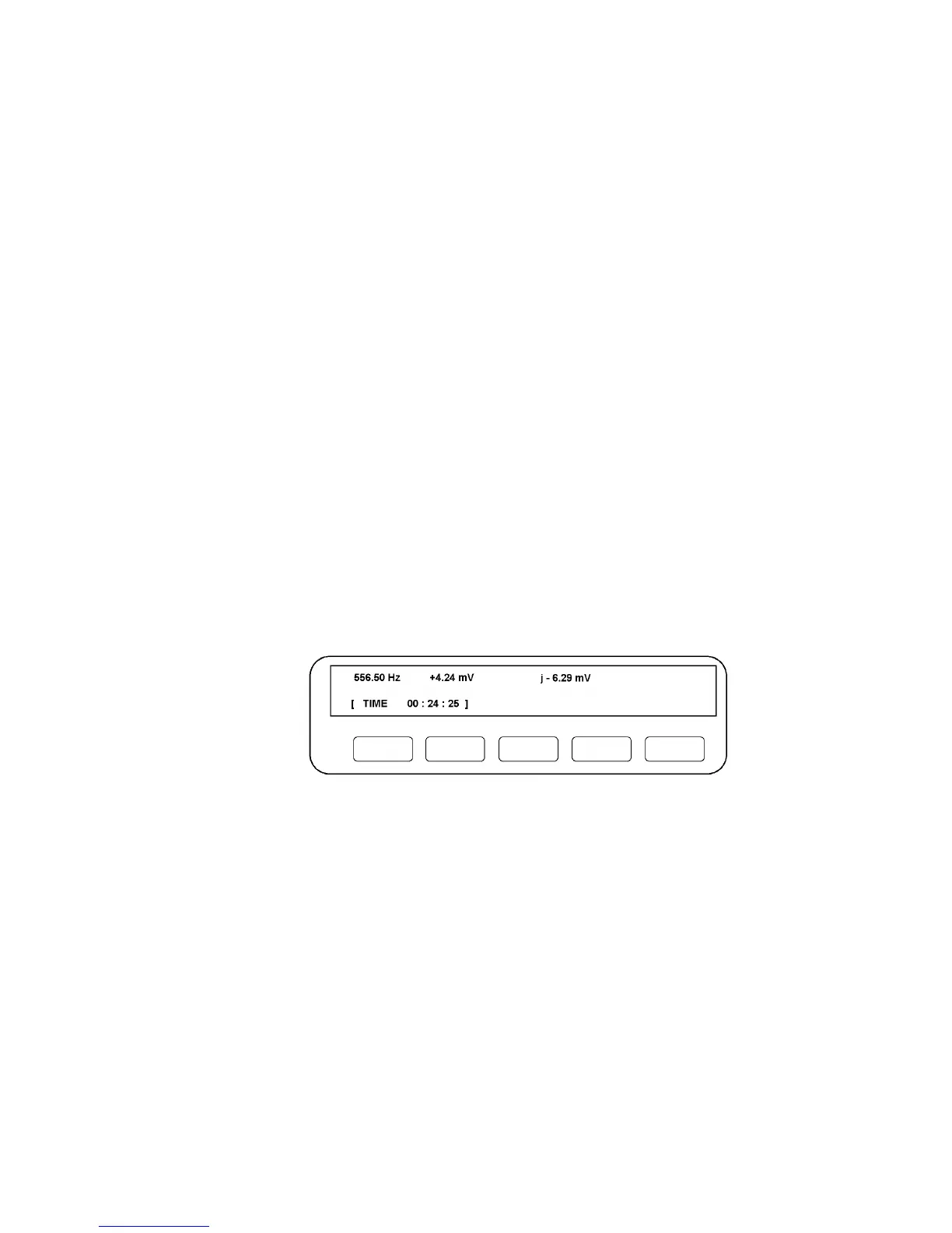
When RECYCLE is pressed, the Display will resemble Fig. 9.2, assuming that the
chosen presentation of results is the a + j b form.
Figure 9.1 - Typical Display Analyzers Running.
The three entries in the top half of the Display show respectively Generator frequency,
the in-phase part of the reading (+4.24 mV) and the quadrature component (j - 6.29mV).