The Display Menu and Mini Status 1250 Frequency Response Analyzer
7-2 CHFR/1250/2
7.1 INTRODUCTION
In the default state the Display uses Channel 1 Analyzer as its source, and presents the
readings in cartesian (a+jb) form. By using the DISPLAY/PLOTTER MENU key, in
conjunction with its associated soft keys, different sources and co-ordinates can be
selected.
Display Areas
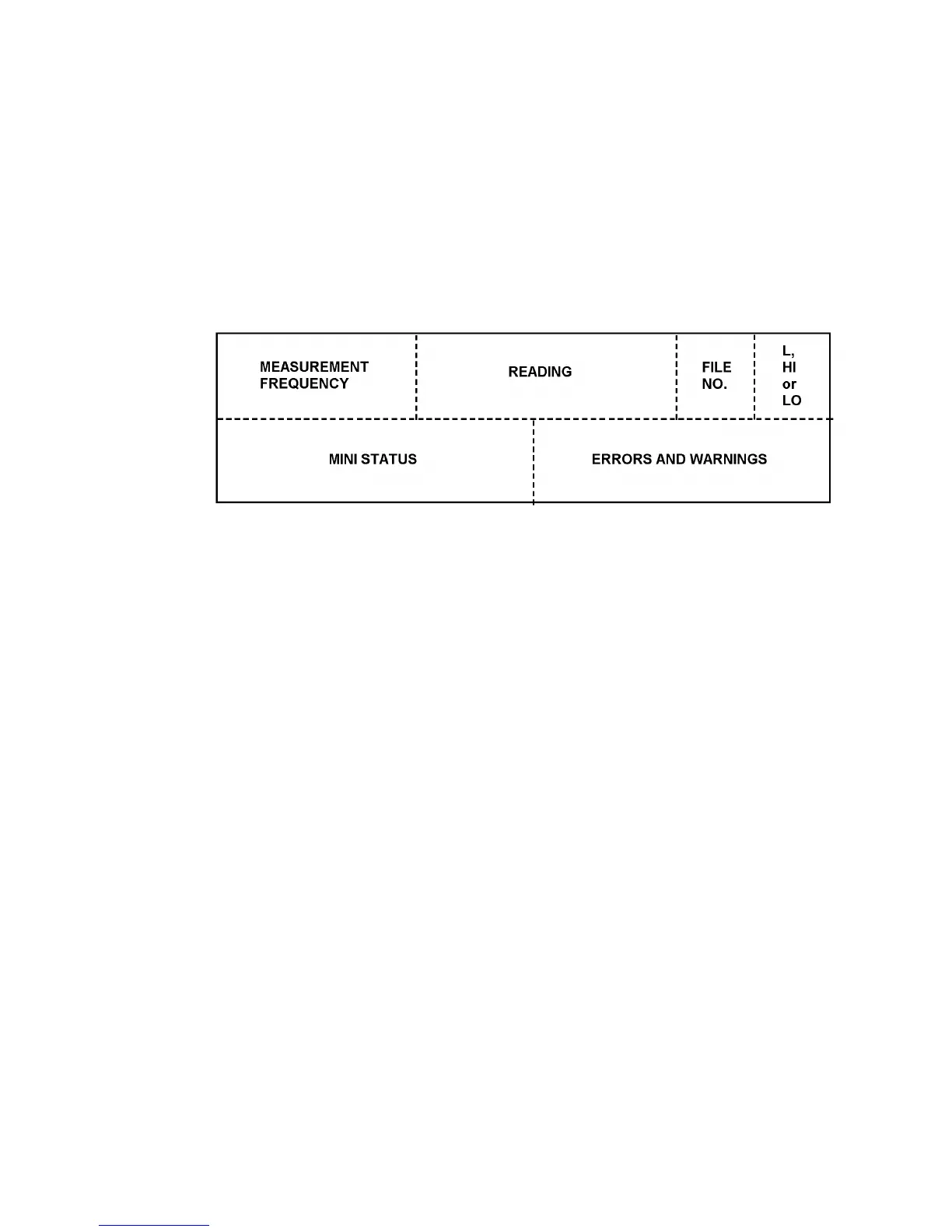
Specific areas of the display are allocated to particular types of message, as shown in
Figure 7.1.
Figure 7.1 - Allocation of Display Areas
Measurement Frequency
This is the frequency at which the measurement was made, which, in the case of a
harmonic of order measurement, is not necessarily the same as the Generator
frequency.
Reading
This is the result of the measurement; the user may choose the co-ordinates as listed in
section 3.
File number
This area is blank unless data is being viewed from the File, in which case a number
from 1 to 470 will be displayed. This number indicates the relevant line in the File, as
explained in Chapter 12.
Limit High or Low
This area is blank unless limits have been applied to the readings by using the
FUNCTION key, as described in Chapter 10.
Mini status
This is explained in section 4.
Note: when no data is output to the Display (Chapter 12 Section 1.2) no mini status
messages will appear in this area.
Errors and Warnings
A list of these, with explanations is given in Chapter 11, Section 2.
Note: when no data is output to the Display (Chapter 12 Section 1.2) no errors or
warnings will appear in this area.