The RS423 and GPIB Ports. Remote Control 1250 Frequency Response Analyzer
13-4 AMK/1250/4
13.2 CONNECTIONS
Connection to the GPIB is made via the 24-way connector on the rear panel of the 1250;
see Fig. 13.2. The pin connections conform to the IEEE 488-1978 standard.
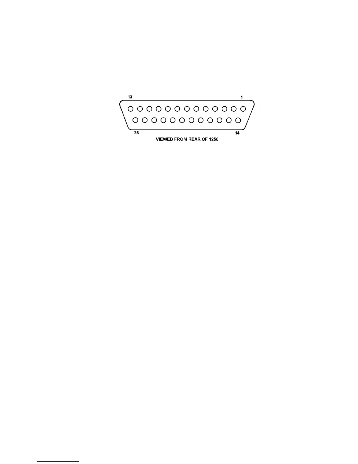
Connection to the RS423 Serial Interface port is made via the 25-way sub-miniature D-
type connector on the rear panel, see Fig. 13.2. The pin connections are shown in Fig.
13. 1.
Figure 13.1 - RS423 Serial Interface Connector
Pin 1 = Ground
Pin 2 = Serial Data to 1250
Pin 3 = Serial Data from 1250
Pin 7 = Ground
The following additional facilities are also available:
Pin 4 = RTS (Request To Send)
Pin 5 = CTS (Clear to Send)
Pin 6 = DSR (Data Set Ready)
Pin 8 = DCD (Data Carrier Detect)
Pin 20 = DTR (Data Terminal Ready)
These facilities are all fully defined in the standards quoted in Section 1.
13.3 RS423 BAUD RATE
The RS423 baud rate is internally selectable on the Processor pcb 22, next to the Power
Supply.
A jumper located next to the light emitting diodes enables selection of baud rates
between a minimum of 110 and a maximum of 9600 baud. The factory setting is 300
baud.
CAUTION: The General Safety Precautions listed in Section 2 of Chapter 2,
"Installation", must be observed; in particular Precaution 6 relating to the opening of
covers and removal of parts.
13.4 RS423 INPUT COMMAND TERMINATOR CHARACTER;
RS423 CHARACTER FRAME
The RS423 Command Code terminator character is fixed as CR (Carriage Return).
The RS423 Character Frame is always:
8 bit + no parity + stop bit.