1250 Frequency Response Analyzer The RS423 and GPIB Ports. Remote Control
AMK/1250/4 13-5
13.5 GPIB SWITCHES
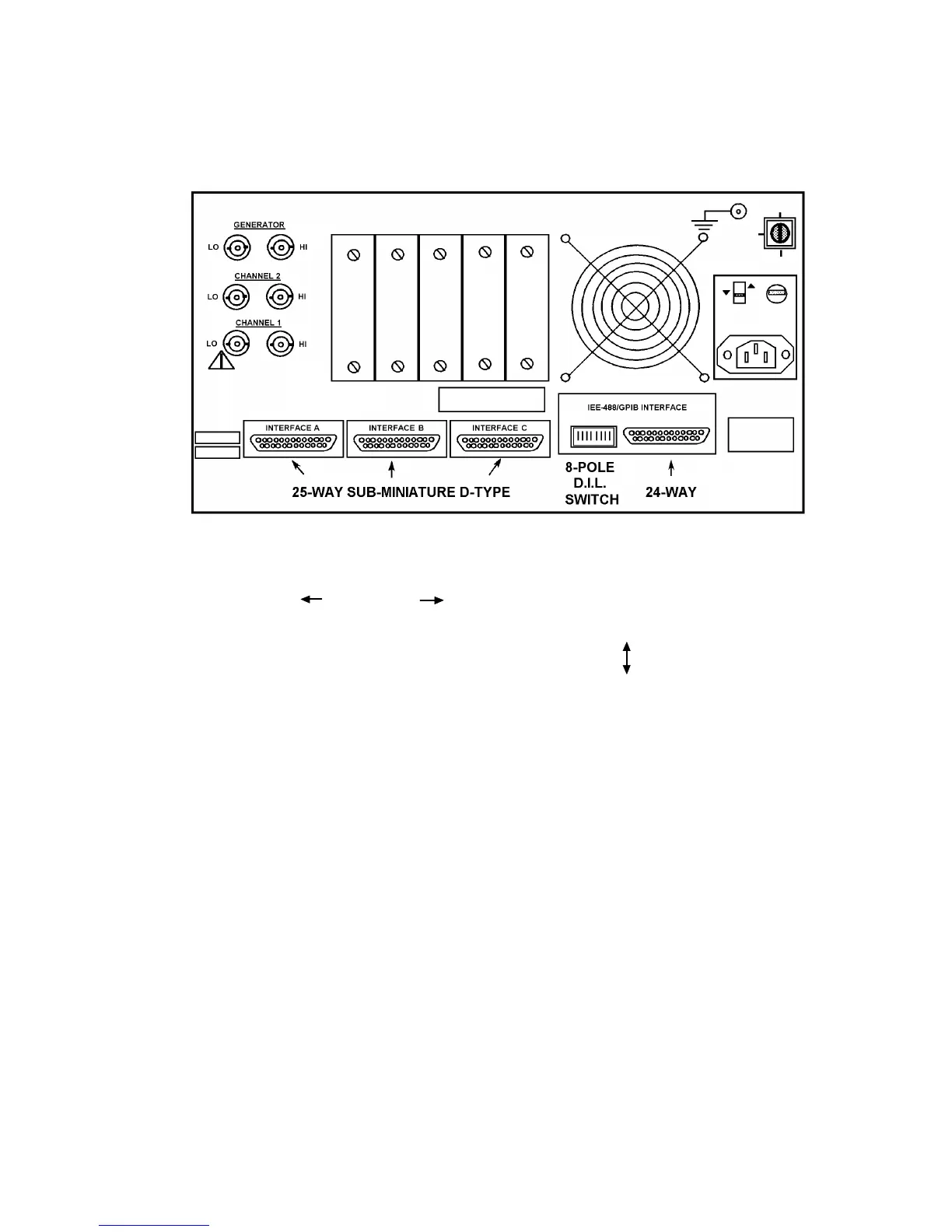
There are eight switches on the rear panel of the 1250, as shown in Fig. 13.2. These
switches must be set before the instrument can be used in a GPIB system.
Figure 13.2 - 1250 Rear panel
The eight switches are allocated as follows:
ADDRESS
1 2 4 8 16 F1 F2 TALK OFF
ONLY
ON
The first five switches select the GPIB address of the 1250. Switches F1and F2 set up
the Command Terminator characters. The last switch sets the mode of the GPIB
operation to Talk Only or normal Talker/Listener.
Once the switches have been set, the 1250 must "read" them, so that their settings can
be implemented. The switches are read automatically on "power on" or when INITialise
or BREAK is pressed. If the switches have to be altered after the 1250 has been set up,
pressing BREAK will enable the new configuration to be read without disturbing any
other data within the instrument, apart from the Serial Poll STATUS BYTE, as explained
in Section 13. 1.