1250 Frequency Response Analyzer Options
AMK/1250/2 15-5
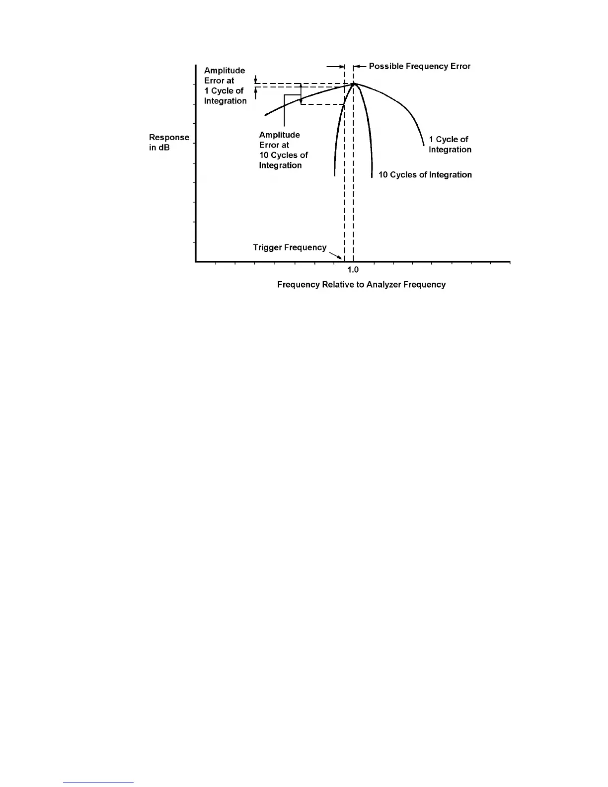
Fig. 15.2 - Possible Amplitude Errors in Ratio Mode
Any difference between the trigger frequency and the frequency to which the Analyzers
have been set will prevent the measured signal coinciding with the peak of the Analyzer
response characteristic. The errors so produced become much worse as the number of
cycles of integration is increased. It is therefore inadvisable to exceed 10 cycles of
integration.
By using Order Analysis it is possible to measure at harmonics of the triggering
frequency without the disadvantages of Ratio mode mentioned in this section. See
Section 1.9 below, "Measuring Harmonies: Use of Order Analysis".
IMPORTANT NOTE
The user must define the point on the incoming waveform at which triggering is to occur.
This is achieved by means of the LEVEL and SLOPE controls, as explained in Section
1.6. These controls must be set before the 1250 is instructed to start measuring, and
must not be altered during a measurement.
Ensure that the Mini Status Display (Chapter 7 Section 4) is showing the message
[SYNC LOCKED] before measurement commences.
15.1.6 THE SYNCHRONISER MENU
Access is gained to the Synchroniser Menu soft keys by pressing GENERATOR MENU
followed by SELECT [ ].
The five soft keys are:
LEVEL. This control is used in conjunction with the SLOPE key to select the point on
the incoming synchronising waveform at which triggering is to occur. Choice of trigger
point is illustrated in Fig. 15.3 below. Enter a voltage value between the limits ±5.1V. If
no value is entered after Initialisation, the 1250 will use the default value of zero. i.e.
synchronise to the zero-crossing point of the waveform.