Options 1250 Frequency Response Analyzer
15-12 AMK/1250/2
15.2 MODULATOR/DEMODULATOR UNIT 12502
15.2.1 INTRODUCTION
This optional unit must be fitted if the 1250 is to make measurements on ac carrier
systems. The 1250 must contain Issue 04, or higher, software; the Issue may be
determined by using Self Test (see Chapter 14, Section 2 "Self Test").
15.2.2 INSTALLATION
A 12502 ordered with a new 1250 will be installed and tested at the factory. When the
12502 is to be added to an existing 1250, installation and calibration must be carried out
by a Solartron engineer.
15.2.3 CONNECTIONS
Two separate carriers can be employed, by using the Carrier 1 and 2 sockets on the rear
panel.
15.2.4 SETTING UP
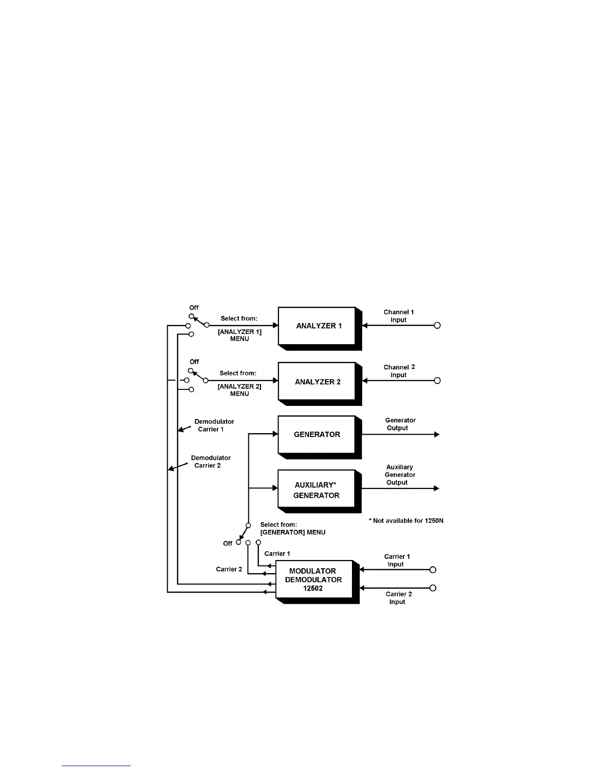
The schematic in Fig. 15.5 shows how the carrier signals can be switched within the
1250.
Fig. 15.5 - Block Schematic of 1250 with 12502
The Generator and Auxiliary Generator are controlled together by the MOD soft key of
the [GENERATOR] MENU, as shown in Chapter 8 "Menu Summary".
Analyzer demodulation is controlled by the DEMOD soft key of [ANALYZER 1] or
[ANALYZER 2] MENU, as shown in Chapter 8.