The 1251 Multichannel Analyzer System 1250 Frequency Response Analyzer
16-4 AMK/1250/1
16.4 CONNECTING UP
16.4.1 SAFETY: CONNECTING THE AC MAINS
The safety precautions and connecting procedures given in Chapter 2 for the 1250 FRA
apply equally to each of the 1251 Units.
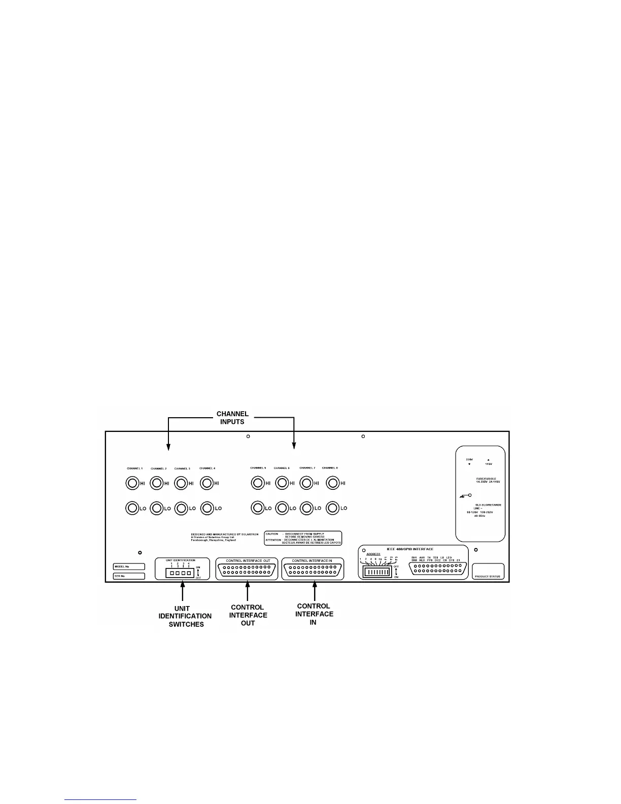
Note: Setting the Unit Identification Switches. Before the system is switched on, the
Unit Identification switches on the rear panel of each 1251 Unit in the system must be
correctly set. Otherwise, measurements will be lost and circuits in the instruments may
be overloaded. Section 5 describes how to set these switches.
16.4.2 CONNECTING UP THE 1250-1251 INTERFACE BUS
1. Plug the female connector on the ribbon cable into the Interface B connector on the
rear panel of the 1250 FRA.
2. Plug the other end of the ribbon cable into the first of the 1251 Units, via the
connector labelled Control Interface In mounted on the rear panel of each 1251
Unit, as shown in Fig. 16.2.
3. If a second 1251 Unit is to be used, plug the 25-way connector of another ribbon
cable into the connector labelled Control Interface Out on the rear panel of the first
1251 Unit. Then connect the other end of this cable to the second 1251 Unit via its
Control Interface In socket, as in step 2.
4. Connect up further 1251 Units in the same way.
Fig. 16.1 above shows which connections are used in the 1250-1251 Interface Bus. The
host 1250 Interface B connector is labelled "IB"; the 1251 Control Interface In
connectors are labelled "IN", and the Control Interface Out connectors are labelled
"OUT".
Fig. 16.2 - 1251 Rear Panel