Options 1250 Frequency Response Analyzer
15-6 AMK/1250/2
COUPLING. May be DC or AC, the former being the default state. AC coupling should
not be used at low frequencies, as defined in the Specification, Chapter 17.
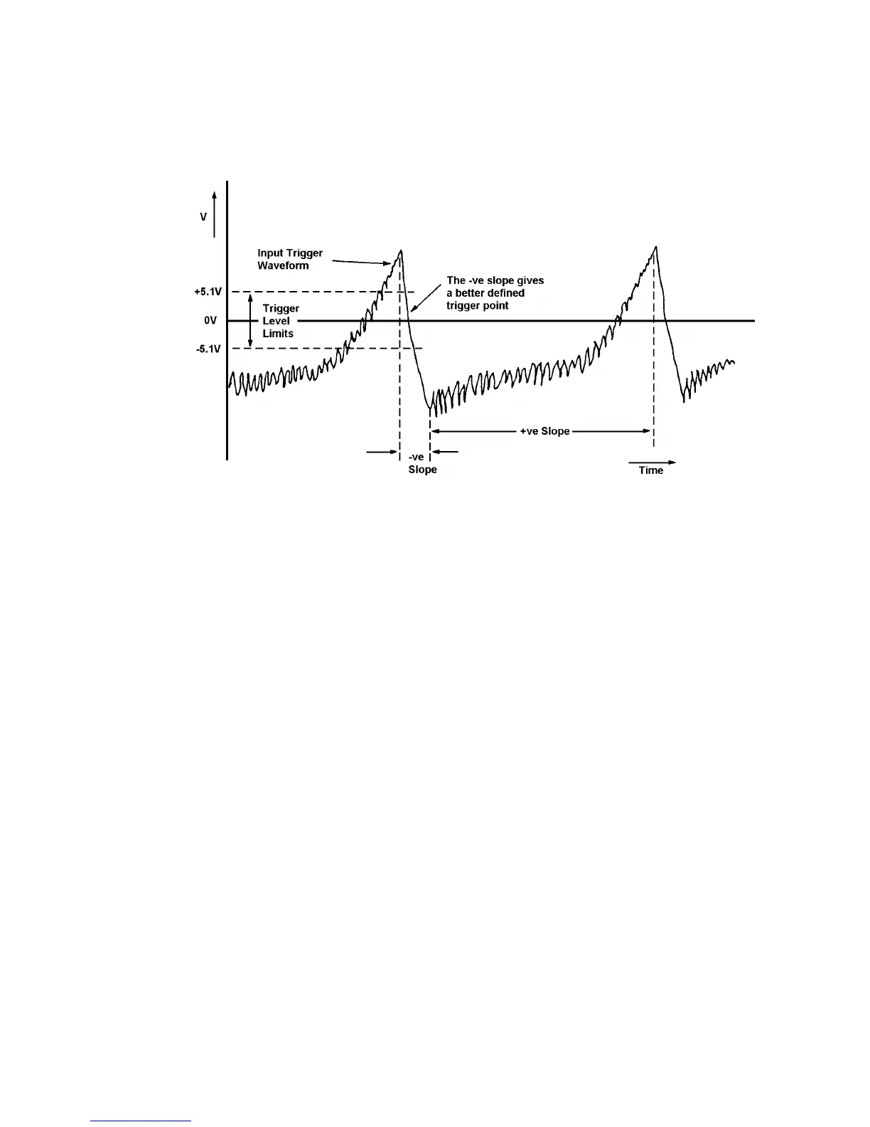
SLOPE. Maybe +ve or -ve, as illustrated in Fig. 15.3 below. Select and enter the slope
which produces the best defined trigger. The default state selects +ve slope.
Fig. 15.3 - Choice of Trigger Point
The minimum useable trigger signal amplitude is 250mV peak to peak.
To allow for hysteresis, when triggering from the positive slope the selected trigger point
must be at least 75mV below the positive peak of the signal and at least 175mV above
the negative peak. When triggering from the negative slope, the selected trigger point
must be at least 175mV below the positive peak of the signal and at least 75mV above
the negative peak.
RATIO. The Ratio mode is explained in Section 1.5 "Modes of Operation". Having
pressed the RATIO key, enter the decimal value of the required multiple or sub-multiple
of the incoming trigger signal frequency. The RATIO and SYNC keys interact as shown
in Fig. 15.4 below.
SYNC. This key acts as the Synchroniser on/off control. There are two "on" modes,
[loose lock] and [tight lock], both explained in Section 1.5 "Modes of Operation". The
SYNC and RATIO keys interact with the [ANALYZER COMMON] HARMONIC key, as
shown in the table below.