Options 1250 Frequency Response Analyzer
15-4 AMK/1250/2
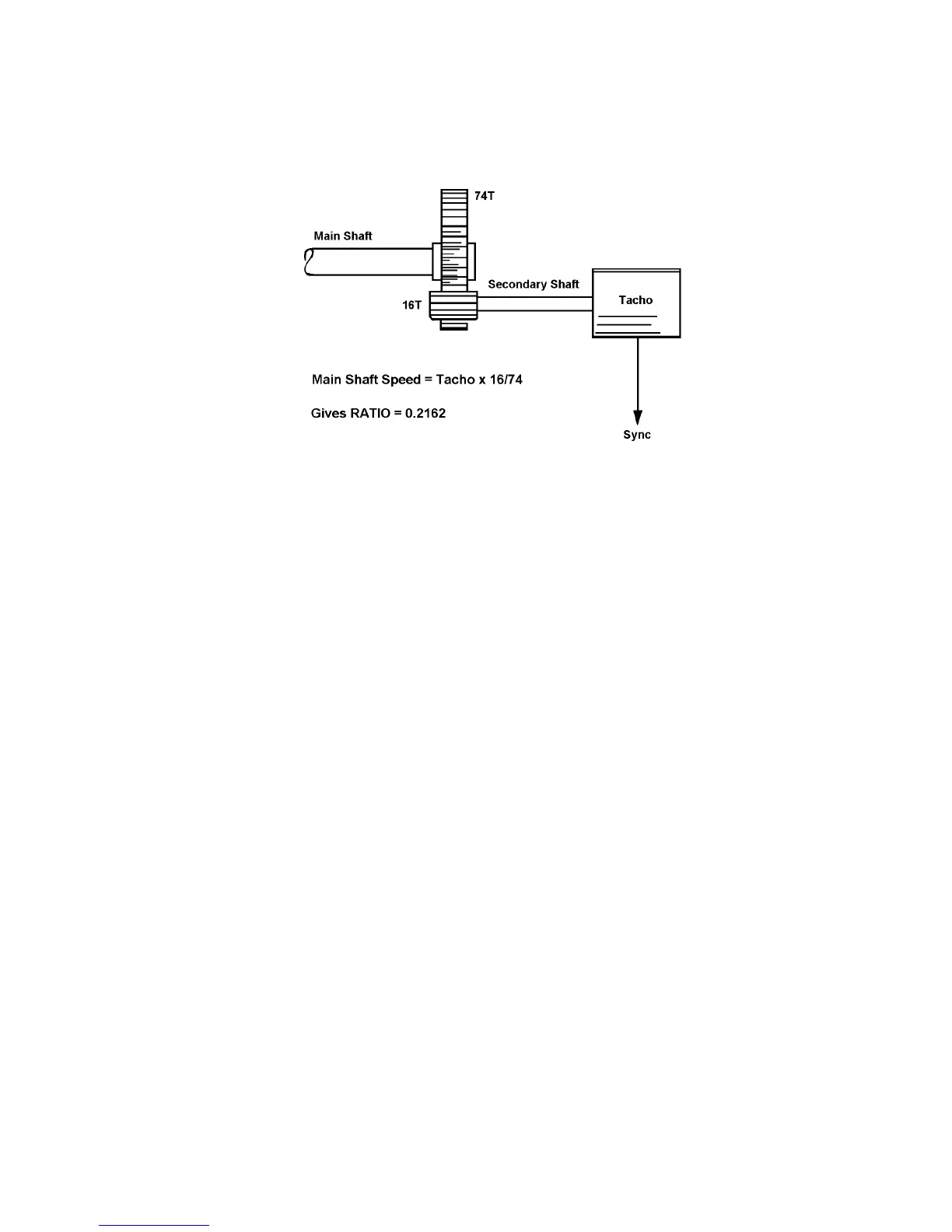
b. Where no direct connection to the desired trigger signal source is possible. An
example of this is shown in fig. 15. 1, where the rotational speed of the main shaft
can only be measured indirectly via a tachometer connected to a geared secondary
shaft.
Fig. 15.1 - Use of RATIO Mode for Indirect Synchronising
When the decimal value of the gear ratio is entered into the 1250, the instrument
computes the rotational frequency of the main shaft, and synchronises the
measurements to this frequency rather than that of the secondary shaft.
As it is not possible to phase lock the Analyzers to the fundamental trigger source,
absolute phase readings are meaningless in this mode. However, single-channel
amplitude measurements can be made, preferably using Polar (r, θ) co-ordinates, and
ignoring the θ value. Point-to-point measurements permit meaningful phase readings to
be taken and, as before, will yield lower errors for amplitude readings.
As the phase locked loop is not used in Ratio mode, the measurement frequency cannot
be controlled as tightly as in other modes. The effect of this is illustrated in Fig. 15.2,
which expands part of the graph shown in Chapter 5, Section 2.1.