Installation 1250 Frequency Response Analyzer
2-10 CWB / 1250_Op / Issue 9A
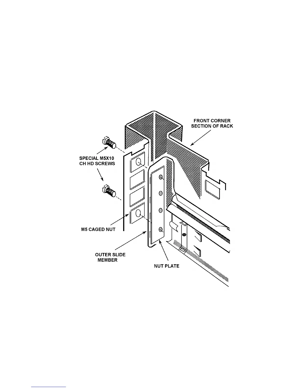
5. Fit the Outer Slide Members (two off) to the rack, as shown in Fig. 2.8
Note that the tapped holes in the nut plate are off centre to provide maximum
lateral adjustment. Fit the plates, as shown, with the holes offset towards the
rack exterior.
Fitting one end of an outer member is facilitated if the other end is supported,
by hooking the bracket at the other end over an M5 screw pushed into the top
caged nut.
Tighten the M5 screws securing each member until it is held moderately firmly
in the rack, approximately in the centre of its travel. The members must,
however, be free enough to take up any adjustment when the 1250 is first
fitted into the rack.
Figure 2.8 - Fitting the outer slide members into the rack