STUDIO INTEGRATION
Audio Connections
A
ll connections to the AWS – apart from the two headphone jacks – are located on the rear panels of the console. The
headphone sockets are located on the Centre Section knee panel.
The console rear panel is fitted with a label which identifies all the connections on the connector panel, and provides the
pinout for each one (the detail is shown opposite). This information is also provided in the Appendices section of this
manual.
All connections are balanced.
All 25-way D-type connectors use screw pillars that utilise the UNC-440 thread.
See the appendices for the pinouts of all audio connectors.
Connecting a Patchbay
The AWS may, of course, be fully or partially integrated to an external patchbay. 3rd party options are available, and SSL
can provide patchbay solutions as cost options – contact your local SSL distributor for further information.
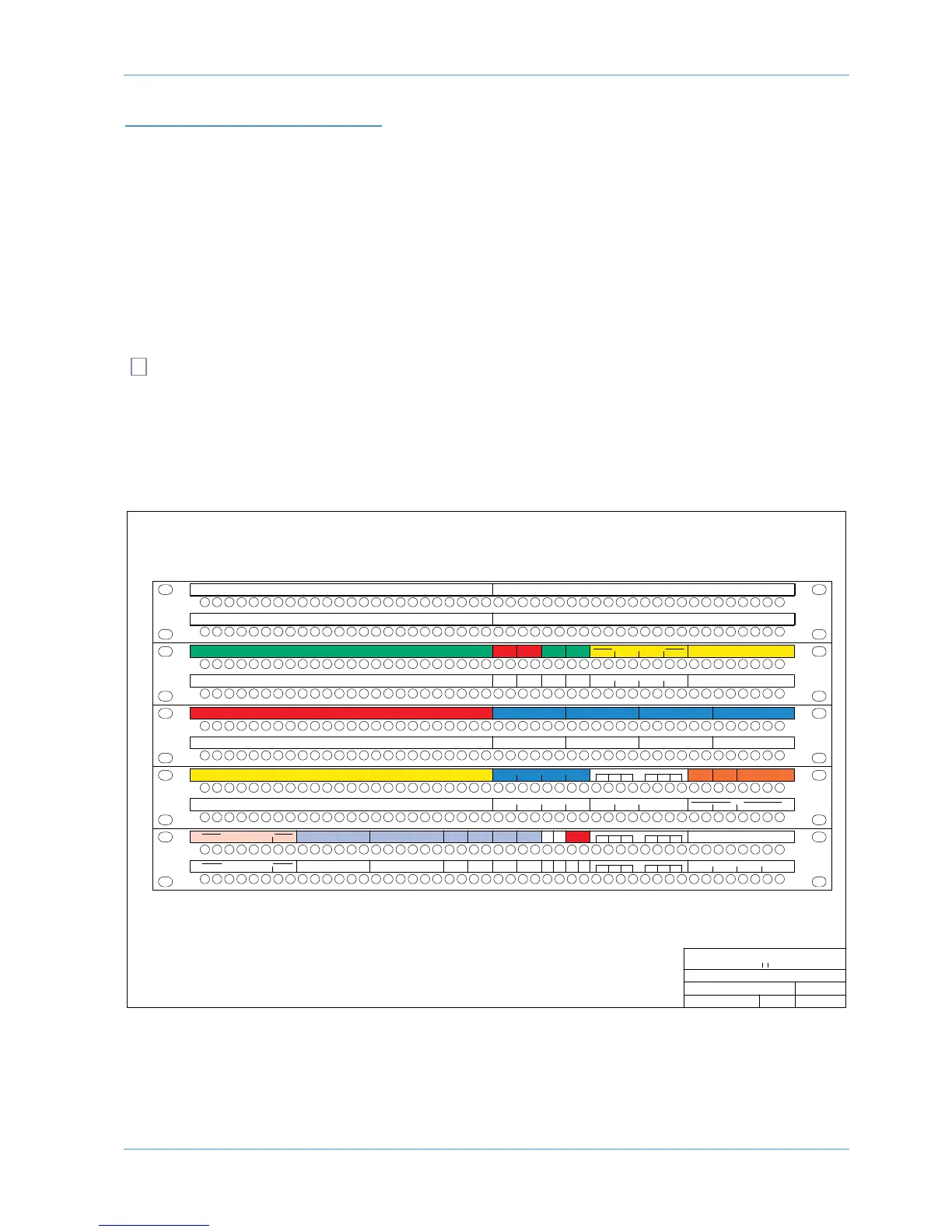
AWS 924 Patchbay Layout Example:
Title:
Client:
Sheet:
Revision:
Drawn by:
Date:
21/09/10
GC
AWS 924 Patch layout proposal
Standard Configuration
924 0.1
Solid State Logic
SOUND V SIION
Notes:
1. Patchrow AB is isolated
2. D31 is linked to C33, 35, 37, 39
3. D32 is linked to C34, 36, 38, 40
4. J31 is linked to J32
5. Links at G33–36, G37–40, J33–36,
J37–40, K33–36, K37–40,
Normalling Information:
Fully normalled: AB 1–24, JK 29
No normalling: AB 25–48, GH 33–40, JK 33–40
All other jacks are half-normalled
1
234
FX IN
L
R
CUE A
L
R
CUE B FX SENDS
1234L RLR
ECHO RETURN IN
1
L 1R 2L 2R 3L 3R 4L 4R
FX OUT
1
L 1R 2L 2R 3L 3R 4L 4R
1L 1R 2L 2R 3L 3R 4L 4R
1
L 1R 2L 2R 3L 3R 4L 4R
EXT B IN
STEREO REPLAY
R
EC
INSERT
R
EC
OUTPUT
LRL
RETURN
R
M
IX
INSERT
M
IX
OUTPUT
L
RETURN
R
DIST IN
LR
M
IX DISTRIBUTION OUT
LRL RL RL R
1L 1R 2L 2R 3L 3R 4L 4R
8 TK RECORDER IN
T
RACK BUS OUT
12345678
12345678
EXT A 6TK 4
L R C LFE LS RS
EXT A 6TK 3
L R C LFE LS RS
EXT A 6TK 2
L R C LFE LS RS
EXT A 6TK 1
L R C LFE LS RS
L
R C LFE LS RS
L
R C LFE LS RS
L
R C LFE LS RS
6 TRACK REPLAY 1
L
R C LFE LS RS
6 TRACK REPLAY 2 6 TRACK REPLAY 3 6 TRACK REPLAY 4
MAIN LS B
L
R
MINI BMAIN LS A
AMP IN
L R C LFE LS RS
L
R
MINI A
L
R
AMP INAMP IN
L
R
AMP IN
L
R C LFE LS RS
L R C LFE LS RS
L
R C LFE LS RS
1
7 18 19 20 21 22 23 249 10 11 12 13 14 15 161 2345678 25 26 27 28 29 30 31 32 33 34 35 36 37 38 39 40 41 42 43 44 45 46 47 48
17 18 19 20 21 22 23 249 10 11 12 13 14 15 161 2345678 25 26 27 28 29 30 31 32 33 34 35 36 37 38 39 40 41 42 43 44 45 46 47 48
DIRECT OUTPUTS
9
10 11 12 13 14 15 161 2 3 4 5 6 7 8 17 18 19 20 21 22 23 24
CHANNEL INSERT SENDS
1
7 18 19 20 21 22 23 249 10 11 12 13 14 15 161 2345678 25 26 27 28 29 30 31 32 33 34 35 36 37 38 39 40 41 42 43 44 45 46 47 48
17 18 19 20 21 22 23 249 10 11 12 13 14 15 161 2345678 25 26 27 28 29 30 31 32 33 34 35 36 37 38 39 40 41 42 43 44 45 46 47 48
1
7 18 19 20 21 22 23 249 10 11 12 13 14 15 161 2345678 25 26 27 28 29 30 31 32 33 34 35 36 37 38 39 40 41 42 43 44 45 46 47 48
17 18 19 20 21 22 23 249 10 11 12 13 14 15 161 2345678 25 26 27 28 29 30 31 32 33 34 35 36 37 38 39 40 41 42 43 44 45 46 47 48
17 18 19 20 21 22 23 249 10 11 12 13 14 15 161 2345678 25 26 27 28 29 30 31 32 33 34 35 36 37 38 39 40 41 42 43 44 45 46 47 48
17 18 19 20 21 22 23 249 10 11 12 13 14 15 161 2345678 25 26 27 28 29 30 31 32 33 34 35 36 37 38 39 40 41 42 43 44 45 46 47 48
MIC LINES USER OPTION
9 10 11 12 13 14 15 161 2 3 4 5 6 7 8 17 18 19 20 21 22 23 24 9 10 11 12 13 14 15 161 2 3 4 5 6 7 8 17 18 19 20 21 22 23 24
CHANNEL MIC INPUTS
9 10 11 12 13 14 15 161 2 3 4 5 6 7 8 17 18 19 20 21 22 23 24 9 10 11 12 13 14 15 161 2 3 4 5 6 7 8 17 18 19 20 21 22 23 24
D
AW OUTPUTS
9 10 11 12 13 14 15 161 2 3 4 5 6 7 8 17 18 19 20 21 22 23 24
CHANNEL LINE INPUTS
DAW INPUTS
9 10 11 12 13 14 15 161 2 3 4 5 6 7 8 17 18 19 20 21 22 23 24
CHANNEL INSERT RETURNS
I
N
LSN
O
UT
LSN
O
UT
T/B OSC
17 18 19 20 21 22 23 249 10 11 12 13 14 15 161 2345678 25 26 27 28 29 30 31 32 33 34 35 36 37 38 39 40 41 42 43 44 45 46 47 48
17 18 19 20 21 22 23 249 10 11 12 13 14 15 161 2345678 25 26 27 28 29 30 31 32 33 34 35 36 37 38 39 40 41 42 43 44 45 46 47 48
L
RLR
F/B A OUT F/B B OUT
L
R
AMP A
L
R
AMP B
MONITOR INSERT SEND
Lt Rt
DECODER
MONITOR INSERT RTN
L R C LFE LS RS
Lt Rt
ENCODER
L
R C LFE LS RS
USER OPTION
A
B
C
D
E
F
G
H
J
K
9 10 11 12 13 14 15 161 2 3 4 5 6 7 8 17 18 19 20 21 22 23 24
9 10 11 12 13 14 15 161 2 3 4 5 6 7 8 17 18 19 20 21 22 23 24
9 10 11 12 13 14 15 161 2 3 4 5 6 7 8 17 18 19 20 21 22 23 24
CUE A 12 34
BUS INJECT IN
FXCUE B