Insert Point
To switch the channel insert into circuit, press the INS IN switch ( in the pictures on the previous page) in the
centre of the EQ section – the LED to its left lights yellow to indicate that it is active. Press PRE to place the insert
immediately before the EQ in the processing chain.
Signal Processing Order
The table below lists the processing order possibilities and the button combinations which accomplish them. The buttons
involved are the IP and OP switch in the DYNAMICS area of the meter bridge, and the insert’s PRE switch, located
above the INS IN switch mid-way down the EQ section:
Processing Order Active Switches
EQ ® Dynamics ® Insert
No routing switches active
Insert ® EQ ® Dynamics
PRE
Dynamics ® EQ ® Insert
IP
Dynamics ® Insert ® EQ
IP + PRE
EQ ® Insert ® Dynamics
OP
Insert ® Dynamics ® EQ
OP + PRE (948)
Insert ® EQ ® Dynamics
OP + PRE (924)
A
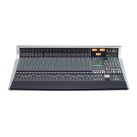
WS 948
When in Stereo channel mode, the insert send and return is stereo. In In-line modes, the left insert connections are used
for the primary channel path and the right connections for the Monitor path. The active insert is then selected via the
Channel Setup screen, described on Page 3-4.
3
Analogue Operations
Page 3-8 AWS 924-948 Owner’s Manual
 Loading...
