Patchbay Guidelines
Instrument Inputs (AWS 924 Only)
It is not recommended that the ‘Instrument’ inputs are broken out to a patchbay. These inputs are unbalanced and have a
high input impedance so, to help avoid the pickup of noise and interference, cable lengths should be kept at short as possible.
Line Level Input/Outputs
All other analogue inputs and outputs can be connected via a patchbay. It is recommended that the cable shield is connected
at the console end and disconnected at the patch row to avoid ground loops. Wiring to the installation should normally have
t
he shield connected to the patch row. The shield connection of all jacks should be linked together (note that patch rows
with solid metal front panels will automatically do this) and then linked to a common star point on the patchbay. This
starpoint can then be returned – via a thick grounding cable (6mm sq. or greater) – to the chassis stud on the rear of the
AWS console. This will reduce the risk of earth loops within the installation.
The screen pins of all analogue inputs and outputs – with the exception of the microphone inputs – are connected directly to
the chassis of the AWS924/48.
Mic Inputs
If Microphone inputs are to be connected via a patchbay, the type of patch-row used should be of the insulated variety
where the jack screens are not connected to the main body of the patch-row – there are commercially available patch-rows
that meet this requirement. The ground connection from each microphone must be linked through the patch jacks to the
XLR on the back of the console without interruption.
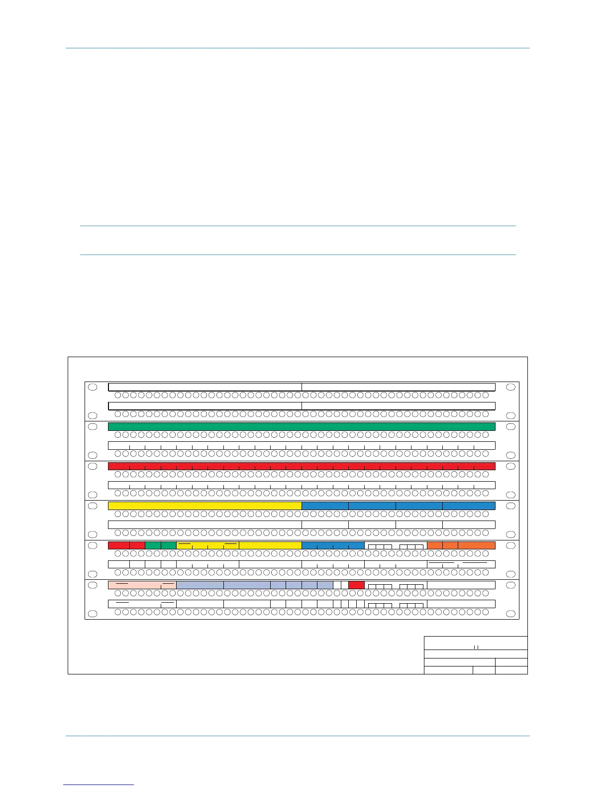
AWS948 Patchbay layout Example:
Studio Integration
Page 1-6 AWS 924-948 Owner’s Manual
Title:
Client:
Sheet:
Revision:
Drawn by:
Date:
14/09/10
GC
AWS 948 Patch layout proposal
Standard Configuration
948 0.1
Solid State Logic
SOUND V SIION
MAIN LS B
L
R
M
INI B
MAIN LS A
AMP IN
L R C LFE LS RS
L
R
M
INI A
LR
AMP INAMP IN
LR
AMP IN
L R C LFE LS RS
L R C LFE LS RS
L R C LFE LS RS
17 18 19 20 21 22 23 249 10 11 12 13 14 15 161 2345678 25 26 27 28 29 30 31 32 33 34 35 36 37 38 39 40 41 42 43 44 45 46 47 48
17 18 19 20 21 22 23 249 10 11 12 13 14 15 161 2345678 25 26 27 28 29 30 31 32 33 34 35 36 37 38 39 40 41 42 43 44 45 46 47 48
17 18 19 20 21 22 23 249 10 11 12 13 14 15 161 2345678 25 26 27 28 29 30 31 32 33 34 35 36 37 38 39 40 41 42 43 44 45 46 47 48
1
7 18 19 20 21 22 23 249 10 11 12 13 14 15 161 2345678 25 26 27 28 29 30 31 32 33 34 35 36 37 38 39 40 41 42 43 44 45 46 47 48
DIRECT OUTPUTS
9 10 11 12 13 14 15 161 2 3 4 5 6 7 8 17 18 19 20 21 22 23 24
CHANNEL INSERT SENDS
17 18 19 20 21 22 23 249 10 11 12 13 14 15 161 2345678 25 26 27 28 29 30 31 32 33 34 35 36 37 38 39 40 41 42 43 44 45 46 47 48
1
7 18 19 20 21 22 23 249 10 11 12 13 14 15 161 2345678 25 26 27 28 29 30 31 32 33 34 35 36 37 38 39 40 41 42 43 44 45 46 47 48
1
7 18 19 20 21 22 23 249 10 11 12 13 14 15 161 2345678 25 26 27 28 29 30 31 32 33 34 35 36 37 38 39 40 41 42 43 44 45 46 47 48
1
7 18 19 20 21 22 23 249 10 11 12 13 14 15 161 2345678 25 26 27 28 29 30 31 32 33 34 35 36 37 38 39 40 41 42 43 44 45 46 47 48
1
7 18 19 20 21 22 23 249 10 11 12 13 14 15 161 2345678 25 26 27 28 29 30 31 32 33 34 35 36 37 38 39 40 41 42 43 44 45 46 47 48
1
7 18 19 20 21 22 23 249 10 11 12 13 14 15 161 2345678 25 26 27 28 29 30 31 32 33 34 35 36 37 38 39 40 41 42 43 44 45 46 47 48
MIC LINES USER OPTION
9
10 11 12 13 14 15 161 2 3 4 5 6 7 8 17 18 19 20 21 22 23 24 9 10 11 12 13 14 15 161 2 3 4 5 6 7 8 17 18 19 20 21 22 23 24
CHANNEL MIC INPUTS
9 10 11 12 13 14 15 161 2 3 4 5 6 7 8 17 18 19 20 21 22 23 24 9 10 11 12 13 14 15 161 2 3 4 5 6 7 8 17 18 19 20 21 22 23 24
DAW OUTPUTS
9 10 11 12 13 14 15 161 2 3 4 5 6 7 8 17 18 19 20 21 22 23 24
CHANNEL LINE INPUTS
DAW INPUTS
9
10 11 12 13 14 15 161 2 3 4 5 6 7 8 17 18 19 20 21 22 23 24
CHANNEL INSERT RETURNS
REC
1234
FX IN
LR
CUE A
LR
CUE B FX SENDS
IN
LSN
O
UT
L
SN
O
UT
T
/B OSC
1
234L RLR
5L 5R 6L 6R 7L 7R 8L 8R1L 1R 2L 2R 3L 3R 4L 4R 9L 9R 10L 10R 11L 11R 12L 12R 17L 17R 18L 18R 19L 19R 20L 20R13L 13R 14L 14R 15L 15R 16L 16R 21L 21R 22L 22R 23L 23R 24L 24R
5L 5R 6L 6R 7L 7R 8L 8R1L 1R 2L 2R 3L 3R 4L 4R 9L 9R 10L 10R 11L 11R 12L 12R 17L 17R 18L 18R 19L 19R 20L 20R13L 13R 14L 14R 15L 15R 16L 16R 21L 21R 22L 22R 23L 23R 24L 24R
17 18 19 20 21 22 23 249 10 11 12 13 14 15 161 2345678 25 26 27 28 29 30 31 32 33 34 35 36 37 38 39 40 41 42 43 44 45 46 47 48
17 18 19 20 21 22 23 249 10 11 12 13 14 15 161 2345678 25 26 27 28 29 30 31 32 33 34 35 36 37 38 39 40 41 42 43 44 45 46 47 48
EXT A 6TK 4
L
R C LFE LS RS
EXT A 6TK 3
L
R C LFE LS RS
EXT A 6TK 2
L
R C LFE LS RS
EXT A 6TK 1
L
R C LFE LS RS
ECHO RETURN IN
L R C LFE LS RSL R C LFE LS RSL R C LFE LS RS
6 TRACK REPLAY 1
L R C LFE LS RS
6 TRACK REPLAY 2 6 TRACK REPLAY 3 6 TRACK REPLAY 4
INSERT
REC
OUTPUT
LRL
RETURN
R
MIX
INSERT
MIX
OUTPUT
L
RETURN
R
DIST IN
LR
1L 1R 2L 2R 3L 3R 4L 4R
F
X OUT
1
L 1R 2L 2R 3L 3R 4L 4R
L
RLR
F
/B A OUT F/B B OUT
LR
AMP A
LR
AMP B
C
UE A
1
234
BUS INJECT IN
F
X
C
UE B
MIX DISTRIBUTION OUT
LRL RL RL R
1L 1R 2L 2R 3L 3R 4L 4R
MONITOR INSERT SEND
Lt Rt
DECODER
MONITOR INSERT RTN
L R C LFE LS RS
Lt Rt
ENCODER
L R C LFE LS RS
8 TK RECORDER IN
TRACK BUS OUT
12345678
1 2 3 4 5 6 7 8 1L 1R 2L 2R 3L 3R 4L 4R
1L 1R 2L 2R 3L 3R 4L 4R
EXT B IN
STEREO REPLAY
USER OPTION
33 34 35 36 37 38 39 4025 26 27 28 29 30 31 32 41 42 43 44 45 46 47 48
5L 5R 6L 6R 7L 7R 8L 8R1L 1R 2L 2R 3L 3R 4L 4R 9L 9R 10L 10R 11L 11R 12L 12R 17L 17R 18L 18R 19L 19R 20L 20R13L 13R 14L 14R 15L 15R 16L 16R 21L 21R 22L 22R 23L 23R 24L 24R
A
B
C
D
E
F
G
H
J
K
L
M
Notes:
1. Patchrow AB is isolated
2. K7 is linked to J9, 11, 13, 15
3. K8 is linked to J10, 12, 14, 16
4. L41 is linked to L42
5. Links at J33–36, J37–40,L33–36,
L37–40, M33–36, M37–40,
Normalling Information:
Fully normalled: AB 1–24, LM 29
No normalling: AB 25–48, LK 33–40, LM 33–40
All other jacks are half-normalled