Input configuration
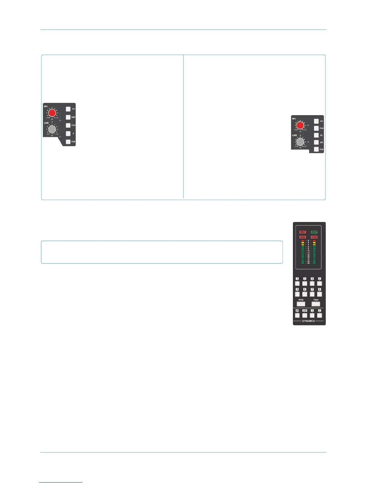
Channel Meters
The 12-segment peak meters at the top of the meter bridge indicate the post-input-trim signal level. Mono
signals use the left hand bargraph. The OVER indicators light red when the level reaches +24dBu.
The bottom segment lights permanently in Analogue Focus mode, to provide clear indication that the
analogue signal, not DAW information, is being displayed.
Dynamics
Any channel can make use of the two compressor/gate modules housed within the AWS centre section.
Press the 1 or 2 switch in the bottom right-hand corner of the meter bridge to insert one of the two
centre section compressor/gate processors into the channel path. For stereo channels, pressing either
button will insert both compressors. These are non-latching buttons that will only function if the selected
processor is not already assigned.
The dynamics are normally inserted post EQ, pre insert. Press the IP switch to place them at the start of the processing
chain, or OP to place them at the end.
See Page 3-22 for details of how to operate the compressor/gate.
AWS 948
Stereo signals use both meters. In In-line modes, the primary channel path signal is shown on the left
and the secondary on the right.
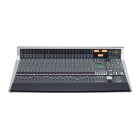
924 and 948
A
WS 924
Switch between the Mic and Line inputs by pressing FLIP.
T
he LED next to each knob lights to indicate it is selected
(red for Mic, green for Line). The INST switch selects a
1MΩ high impedance input (6.35mm jack), suitable for
sources such as guitars.
Adjust the input level using the MIC
(
+12dB to +75dB) or LINE (±20dB,
notched at 0dB) pot. The INST input is
controlled via the MIC pot.
In addition there are switches for phase
reverse (Ø), 48V phantom power and
a 20dB PAD.
A
WS 948
Switch the primary channel path’s input between Mic or
Line by pressing FLIP. The LED next to each knob lights
to indicate it is selected (red for Mic, green for Line). The
r
ight (or monitor) channel path’s input has no input
selection as it is always fed from the same connector when
it is active. If Stereo mode is selected, the inputs are
automatically set to Line.
Adjust the input level using the MIC
(+12dB to +75dB) or LINE (±20dB)
pot. When in stereo mode, both legs of
a stereo line input are adjusted by the
LINE control. In in-line mode, the
monitor path’s input is always at unity
gain.
There are switches for 48V phantom power and a 20dB
PAD. Inputs to both channel paths have phase reverse
switches – LØ acting on the left or primary channel path
input, and RØ acting on the right or monitor path.
924
948
Analogue Operations
Page 3-6 AWS 924-948 Owner’s Manual