DMS-1200 Release 6 Operations Manual
Section 7 – DAS Device Control 59
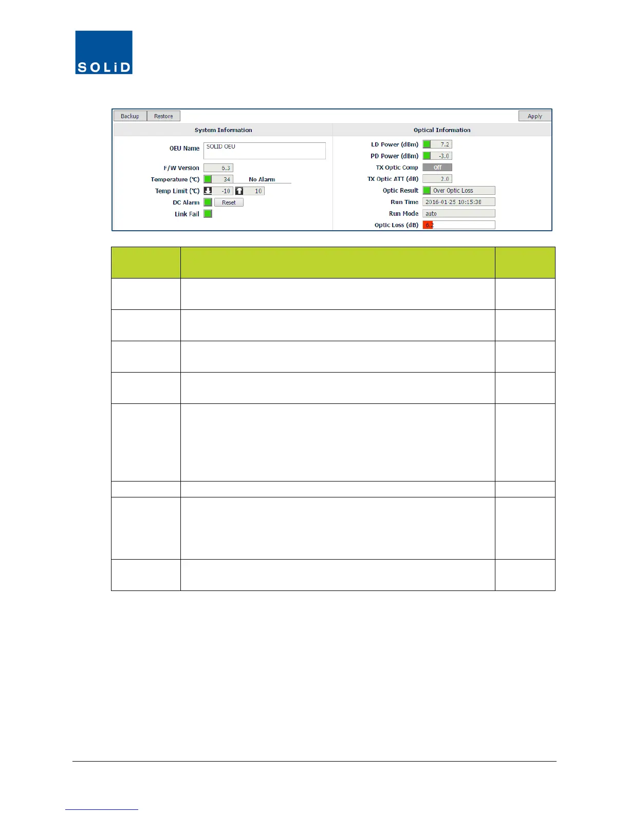
E-Optic Field
Action / Description User
LD Power Displays current laser diode power of E-Optic module. Green =
normal. Red = power is below reference power current.
N
PD Power Displays current photo diode power received from ROU or OEU.
Green = normal. Red = power falls below reference power level.
N
Tx Optic
Click the toggle to turn On/Off the Auto optical loss compensation
function. Turn on for all active optical ports.
Y
Tx Optic ATT
Indicates attenuation for the (RX) receive side of the DOU. Basic
ATT value is 10dB for OM4 modules or 24dB for OM1 modules.
N
Optic Result Shows result after compensating for optical loss:
Success: optical compensation has been successful.
Over Optic Loss: optical loss generated exceeds limits: 6dBo or
more for 4-port DOU (OM4); 11dBo or more for 1-port DOU (OM1).
Fail: Communication between the DOU and ROU has failed.
N
Date / Time when optical compensation was last performed.
Run Mode Optical compensation mode:
Auto: Optical compensation was executed by the CPU
automatically.
Manual: Optical compensation was executed manually by the user.
N
Optic Loss Displays optical loss. Green = optical loss is within tolerance. Red
= optical loss exceeds limits: 9dB for OM1; 4dB for OM4.
N
Table 7.8 – E-Optic Optical Information Setup Screen Fields