DMS-1200 Release 6 Operations Manual
Section 7 – DAS Device Control 74
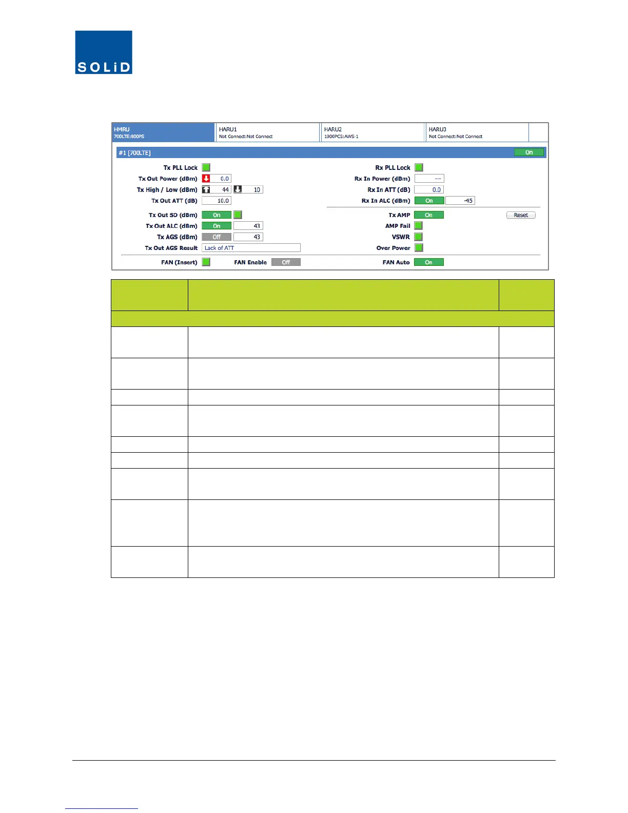
3. Configure the RX Values for the drive unit according to these guidelines:
Field Action / Description
User
Rx PLL Lock Rx Phase Locked Loop status. Green = Normal. Red = PLL
N
Rx In Power Shows Rx input power on that port. Accuracy is ±2dB.
Displays --- when there is no input detected.
N
Shows attenuation level applied to Rx input power.
Rx In ALC Click the toggle to turn On/Off the Auto Limit Control for input
Y
Click Reset to cycle power to reboot the RDU.
Click the toggle to turn On/Off the high power amplifier.
AMP Fail Shows status of amplifier. Green = normal. Red = Power amplifier
loop has failed or unexpected low power has been detected.
N
VSWR Shows status of VSWR (Voltage Standing Wave Ratio). Green =
normal. Red = VSWR level has exceeded the pre-determined
N
Over Power Shows status of Over Power alarm. Green = normal. Red = Output
power level of the power amplifier has exceeded threshold level.
N
Table 7.21 – TiTAN Remote Drive Unit Control Screen Fields – RX Values