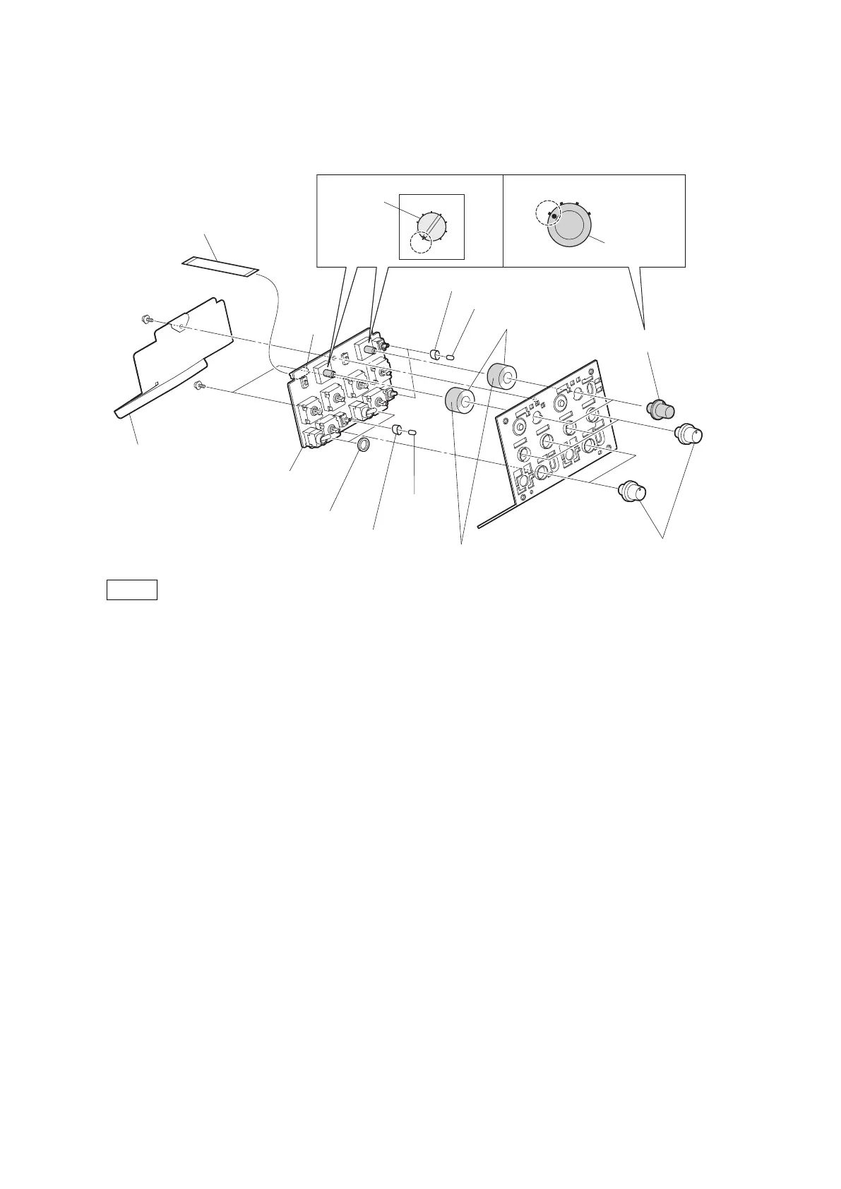
6. Remove the three SW caps, three toggle drop protections, two boron sheets (MIC SW), and the two return SEL
packings.
5
14
23
4
3
2
1
0
9
8
7
6
SW-1530 board
PSW2 x 5
PSW2 x 5
SW caps
Return SEL packings
DC line protection sheet
Return select knobs
Return select
knobs
VR knobs
Toggle drop protections
Switch
Position of switches and return select knobs
SW caps
Adhesive surface
Toggle drop
protection
Boron sheets
(MIC SW)
Flexible flat cable (15 core)
CN1
Notes
• When installing the return select knob and VR knob, apply locking compound to the inside of the knobs.
• When installing the return select knob, set the marks of the switch and the return select knob on the SW-1530
board to the positions shown in the figure.
• When installing the return SEL packing, stick the adhesive surface to the board side.
7. Install the removed parts by reversing the steps of removal.
HDC4300
4-54