Section 4
Replacement of Main Parts
This section explains the replacement procedures of periodic replacement parts, main mechanical parts, and mounted
circuit boards.
4-1. General Information for Parts Replacement
4-1-1. Index
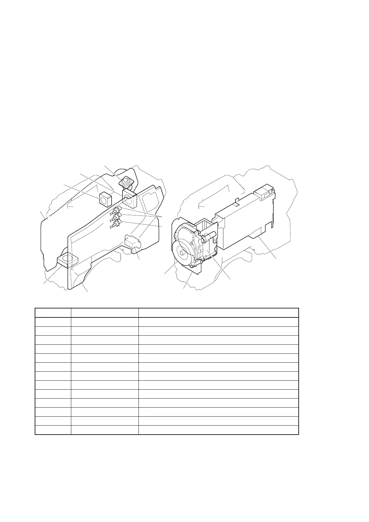
This section describes the replacement procedure of the parts below.
Mechanical parts
(3)
(13)
(4)
(5)
(11)
(6)
(1)
(12)
(2)
(7)
(8)
(10)
(9)
No. Part name Section
(1) Inside Panel Assembly “4-2. Inside Panel Assembly”
(2) Outside Panel Assembly “4-3-1. Outside Panel Assembly”
(3) Optical Multi Cable Assembly “4-3-5. Optical Multi Cable Assembly”
(4) PROMPTER Connector “4-3-6. PROMPTER Connector”
(5) Coaxial Cable “4-3-7. Coaxial Cable”
(6) DC fan (outside) “4-3-3. DC Fan (Outside panel)”
(7) Front Assembly “4-5. Front Assembly”
(8) FD Assembly “4-4. FD (Filter Disk) Assembly”
(9) OHB Assembly “4-6-1. OHB Assembly”
(10) Power Block Assembly “4-8-2. Power Block Assembly (RE-291 Board/PS-836 Board)”
(11) BUILD UP Connector “4-8-13. BUILD UP Connector”
(12) DC Fan (Front) “4-9. DC Fan (Front)”
(13) DC Fan (Rear) “4-10. DC Fan (Rear)”
Mounted circuit boards
After replacing/repairing the mounted circuit boards (or the assembling parts including them), perform the steps after
replacement/repair. (Refer to“1-4. Notes on Board Replacing”)
HDC4300
4-1