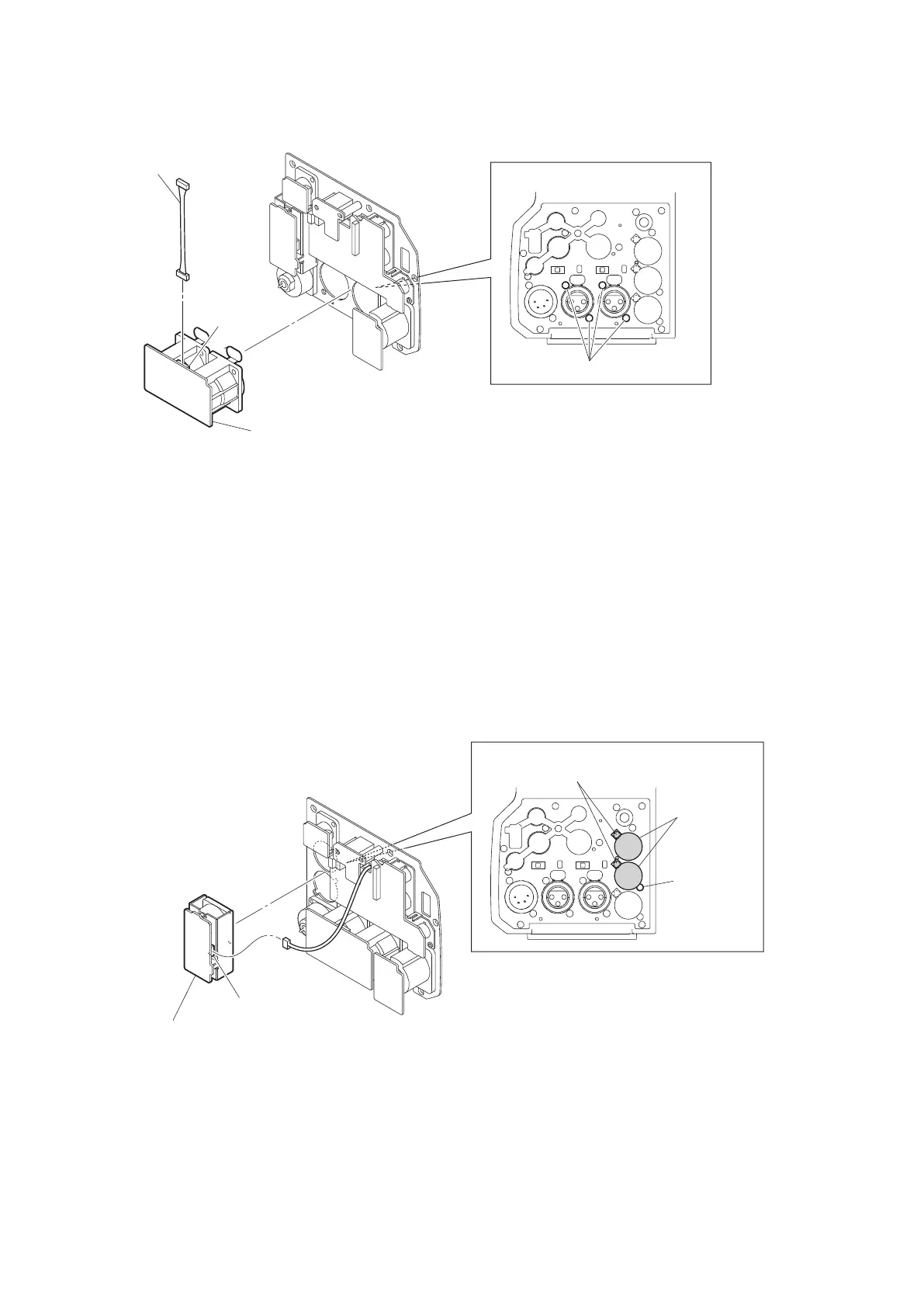
2. Disconnect the harness from the connector (CN1) on the CN-3425 board.
AUDIO IN connector (CN-3425 board)
Harness
CN1
Rear view
B2.6 x 5
3. Install the removed parts by reversing the steps of removal.
4-11-3. PROMPTER/GENLOCK/TEST OUT Connector (CN-3428 Board)
Preparation
1. Remove the MIC panel assembly. (Refer to“4-11-1. CN-3429 Board/CN-3427 Board” on page 4-47 )
Procedure
1. Remove the three screws, and detach the two BNC caps and the PROMPTER/GENLOCK/TEST OUT connector
(CN-3428 board).
2. Disconnect the harness from the connector (CN3) on the PROMPTER/GENLOCK/TEST OUT connector
(CN-3428 board).
B2x5
PROMPTER/GENLOCK/TEST OUT connector
(CN-3428 board)
B2 x 5
BNC cap
Rear view
CN3
3. Install the removed parts by reversing the steps of removal.
4-11-4. REMOTE Connector (CN-3430 Board)
Preparation
1. Remove the MIC panel assembly. (Refer to“4-11-1. CN-3429 Board/CN-3427 Board” on page 4-47 )
HDC4300
4-50