3-20 IGNITION AND ELECTRICAL
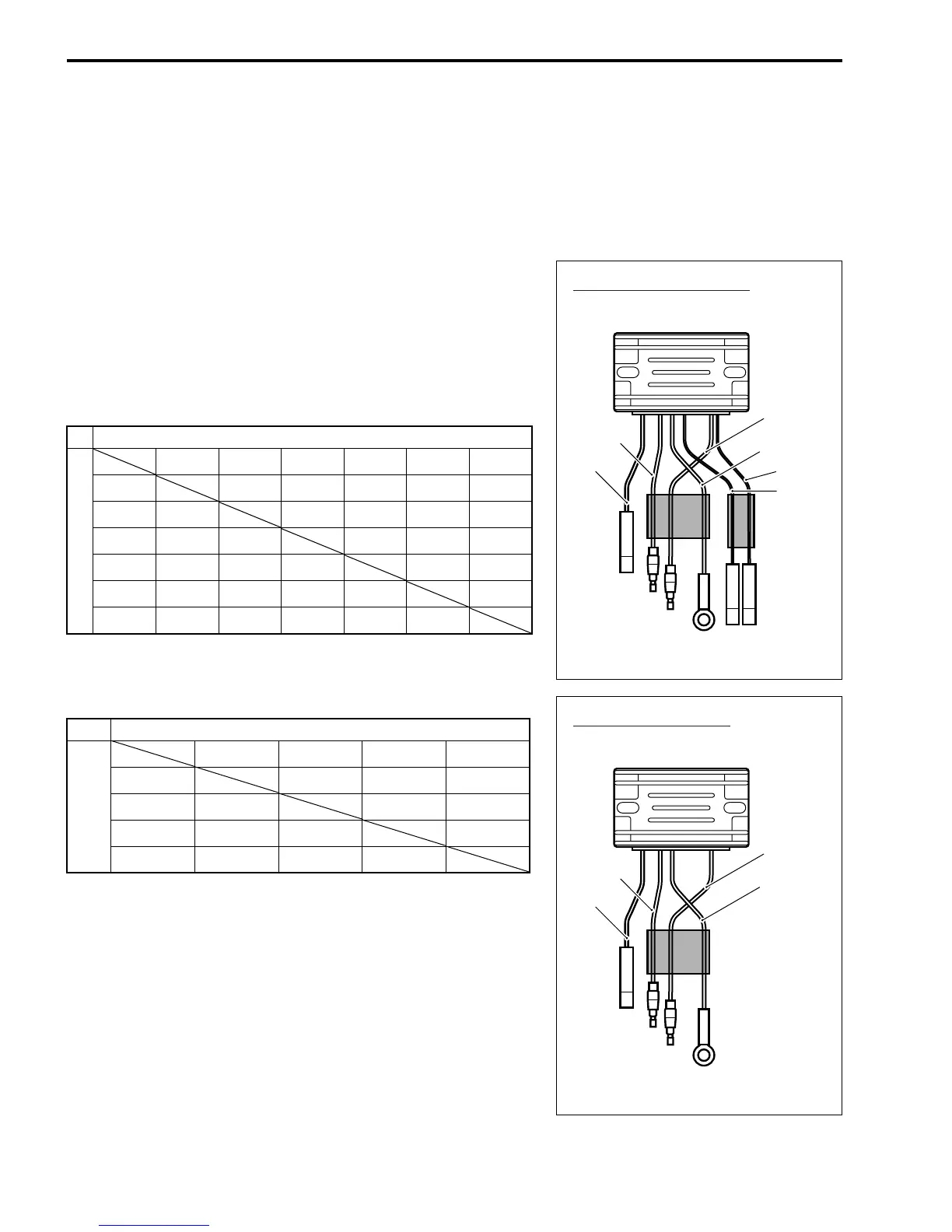
RECTIFIER & REGULATOR
09900-25010: Pocket tester
Tester range: ×1 kΩ (Resistance)
1. Disconnect all lead wires of rectifier & regulator.
2. Measure resistance between leads in the combinations
shown.
NOTE:
The values given below are for a SUZUKI pocket tester.
As thyristors, diodes, etc. are used inside this rectifier & regula-
tor, the resistance values will differ when an ohmmeter other
than SUZUKI pocket tester is used.
Rectifier & regulator resistance:
Remote control model Unit: Approx. kΩ
Tiller handle model Unit: Approx. kΩ
If measurement exceeds specification, replace rectifier & regula-
tor.
Tester probe + (Red)
Tester probe - (Black)
Black White
Yellow 1
Red
Yellow 2 Yellow 3
Black 7 – 11 2 – 4 2 – 4 2 – 3 7 – 11
White
∞
∞∞∞
0
Yellow 1
160 – 240
2 – 4
400 – 600 400 – 600
2 – 4
Red
160 – 240
2 – 4
400 – 600 400 – 600
2 – 4
Yellow 2
∞∞∞∞ ∞
Yellow 3
∞ 0 ∞∞∞
Red
Remote control model
Yellow 1
Black
Yellow 3
Yellow 2
White
Tester probe + (Red)
Tester probe -
(Black)
Black White Yellow Red
Black 7 – 11 2 – 4 2 – 4
White
∞
∞∞
Yellow ∞ 2 – 4 ∞
Red ∞ 2 – 4 ∞
Red
Tiller handle model
Yellow
Black
White