Chapter C Chapter C
Maintenance Mode
90
W301-0411E
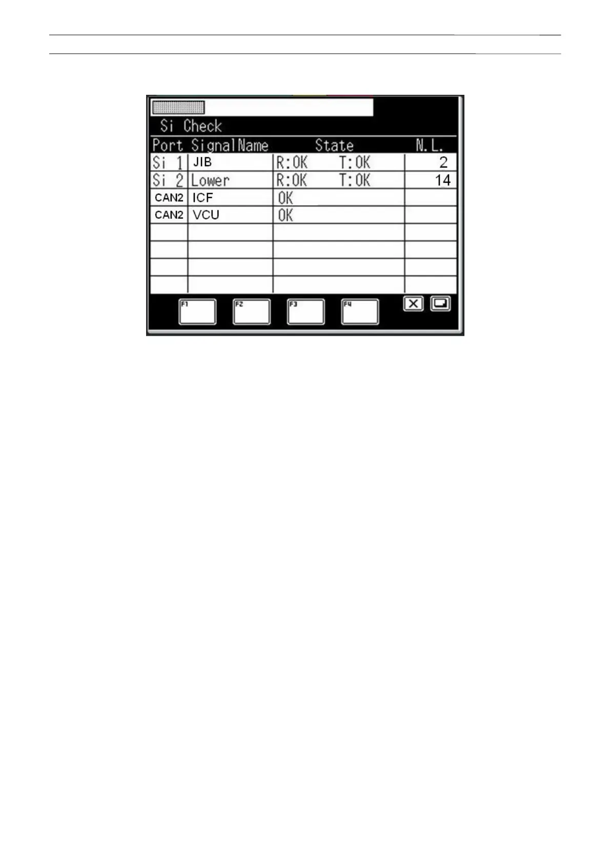
When a node is connected to the CAN, the state of each node is also displayed as shown in Fig. 2.5.2.
Fig. 2.5.2 Si check screen including CAN node state
<Description of display contents>
Port
CAN1 to CAN2: CAN communication port
Signal Name
ICF: Node name of information controller for Telematics
VCU: Node name of controller for vehicle
(Reference: Represents the DCU, and used for the meter panel control.)
State
OK: Normal
NG: Error
N.L.: Noise Level
Value for the data reception failure count (since the power is turned on).
Used as a guideline of the communication state.
 Loading...