65
W301-0411E
Chapter B Chapter B
User Mode
6.3 Drum Indicator Control Function
6.3.1 Outline of Drum Indicator Control Function
The panel LED changes depending on the drum rotation speed of displayed drum. According to the main drum
rotation and auxiliary drum rotation, the Do output (20 ms = 20/1000 second) is performed.
6.3.2 Input
1). #17216-1 Main drum rotation
2). #17216-2
Auxiliary drum rotation
6.3.3 Output
1). #17802-122 Main drum indicator Do output
2). #17708-123
Auxiliary drum indicator Do output
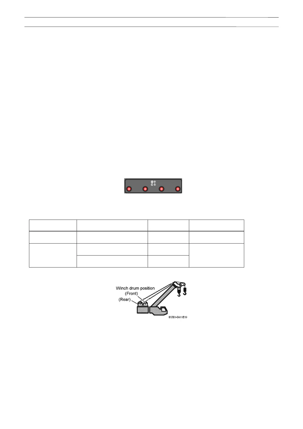
6.3.4 Panel LED Control
According to the rotation of displayed drum, the LED indicators (Fig. 6.3.1) in the AML-C body upper section are
sequentially illuminated.
However with models that winch drum position is selected in the user preset menu, the illumination switching
timing is calculated based on the information described in the table below (Table 6.3.1) according to the selected
winch drum, and the control is performed.
Fig. 6.3.1 Panel drum indicator LED
Table 6.3.1 Models with user preset menu selection, illumination switching timing
(Selection of adjustment method: " Front " ←→ "Front/rear")
Operation status Winch drum position status
Rotation detector
(pulse)
Frequency dividing
Boom lift Front
Main winch
drum
Number of main wire
part-lines
Front
Main winch
drum
Other than
boom lift
Rear
Auxiliary winch
drum
Number of auxiliary
wire part-lines
(Refer to Chapter B, 4.5.6 “Selection of Winch to be use”)
6.3.5 Drum Indicator Do Output Control
The Do (#17802-122) output control corresponding to main drum rotation speed (#17216-1) and the Do
(#17802-123) output control corresponding to auxiliary drum rotation speed (#17216-2) are performed
concurrently. ON is output for 20 ms, and then OFF is output.
6.3.6 Drum Indicator Do Output Restriction
The drum output exceeding the frequency of 7 Hz is stopped, and the output stop status will be maintained until
the frequency becomes to 5 Hz or less.