64
W301-0411E
Chapter B Chapter B
User Mode
6.2 Do Output Abnormality Processing
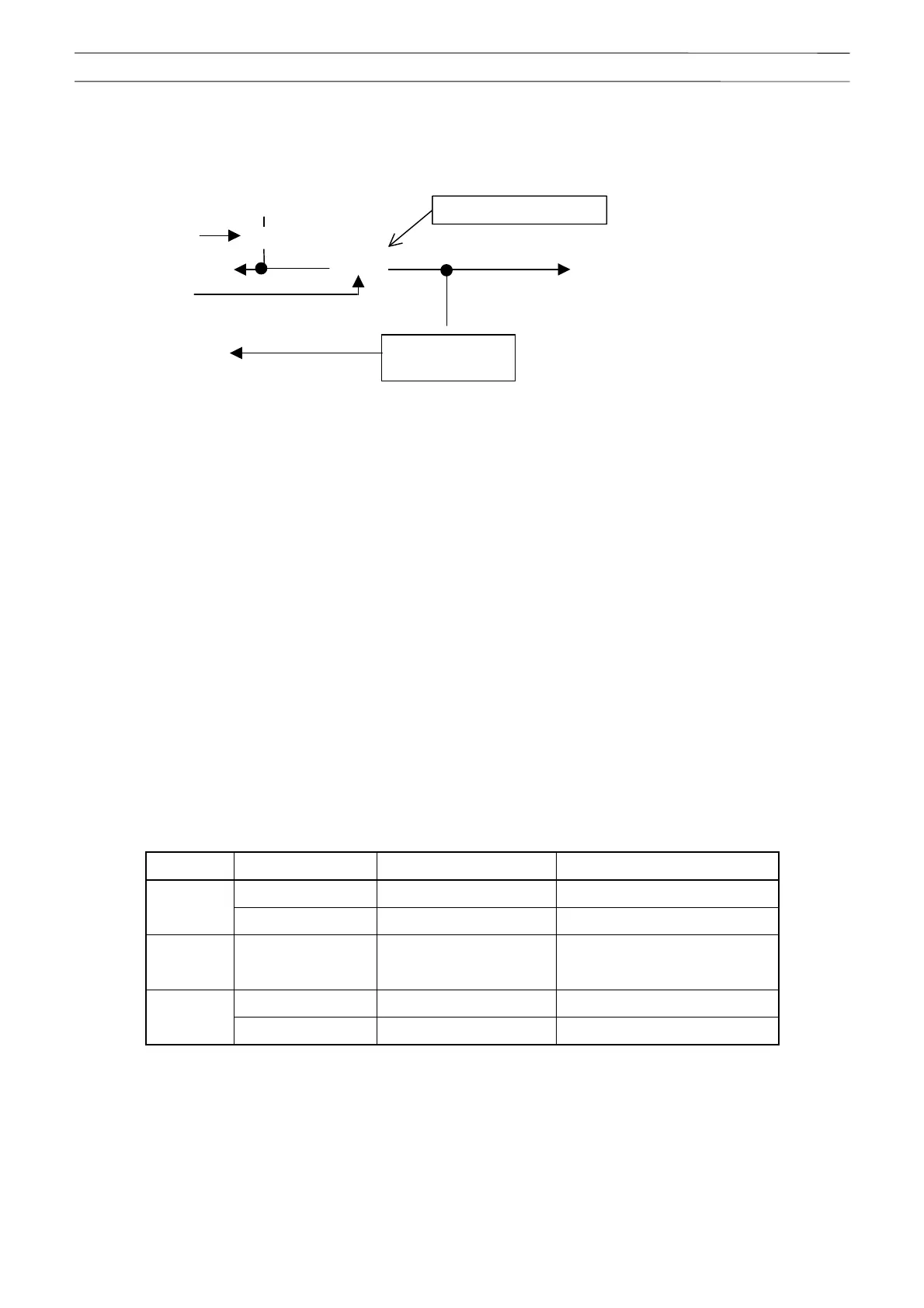
The block diagram below shows the Do highside output.
(1) Do output power abnormality
- In case of Do0 operation failure (Do output power monitor is 18 V or less), an error is displayed.
At the Do0 operation failure, the Do highside ON output abnormality is not displayed.
- As for the Do highside output abnormality processing of (2), the error will not be displayed when Do0 is turned
OFF.
- As for Di, when PTO ON/OFF changeover is possible and PTO is OFF, the abnormality detection is not
performed.
(2) Do highside output abnormality
- When an output abnormality (a contradiction between Do output signal and output monitor signal) occurs to the
Do highside output (Do1 to 8), an error is displayed.
- When the Do output signal is OFF and the output monitor signal is ON, in order to prevent the dangerous
operation caused by the Do highside output clinging (such as FET output short, etc.), the output voltage of Do
highside output (Do1 to 8) is cut by turning OFF Do0.
The table below shows the output status of Do0 output signal with each output abnormality.
Table 6.2.1 Output status of Do0 output signal for each output abnormalities
Do No. Do output signal Output monitor signal Do0 output signal status
On (H) Off (H) ---
Do1
Off (L) On (L) Off
.
.
.
.
.
.
.
.
On (H) Off (H) ---
Do8
Off (L) On (L) Off
- When the Do0 output signal is OFF, the abnormality is not detected for Do output signal ON and output
monitor signal OFF.
- To restore from the output voltage cutoff of Do highside output (Do1 to 8), turn OFF the machine main power
and then ON again because the error status is retained.
+24V
RY
Rela
Do0 output signal
FET
Output monitor
circuit
Do output signal
Output monitor signal
Do highside output
Do out
ut
ower monito
(Field Effect Transistor)