Chapter A Chapter A
Components of AML System
25
W301-0411E
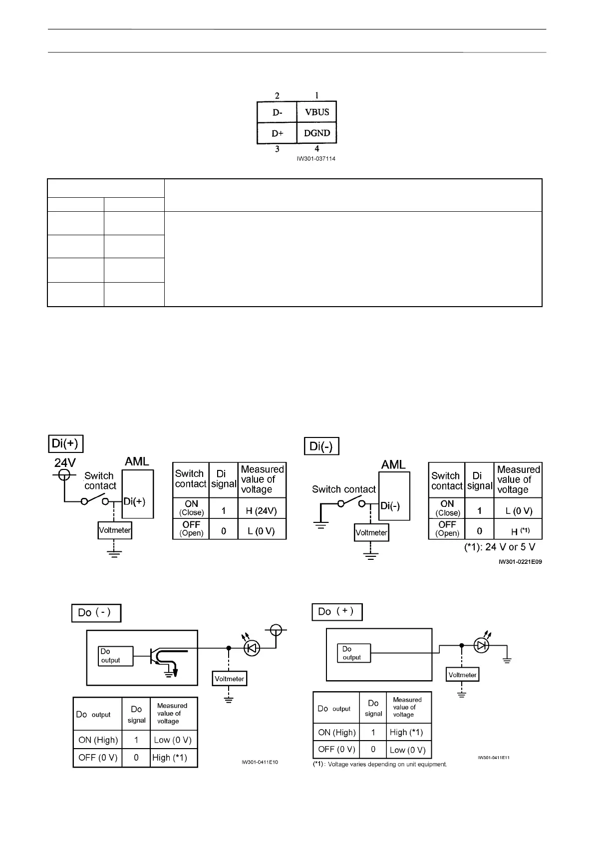
2.1.10 CN9 (USB) Connector (4-Pin)
CN9 connector
Pin No. Name
Signal names and functions
1 VBUS
2 D-
3 D+
8 DGND
(Spare)
2.1.11 Explanation of the Signals (Di, Do)
[NOTICE]
¡ For the detailed electrical circuit, refer to the service manual (circuit diagrams) for each model.
1. Di signals
Di (+) and Di (-) indicate the digital input signal with the connection status shown in the figure below.
2. Do signals
Do (+) and Do (-) indicate the digital output signal with the connection status shown in the figure below.