Chapter C Chapter C
Maintenance Mode
133
W301-0411E
4.5 CPU State Indicator LED
The AML has three LEDs on the circuit board whose illumination is controlled by software. Depending on the
lighting status of each LED, the AML operating status can be checked.
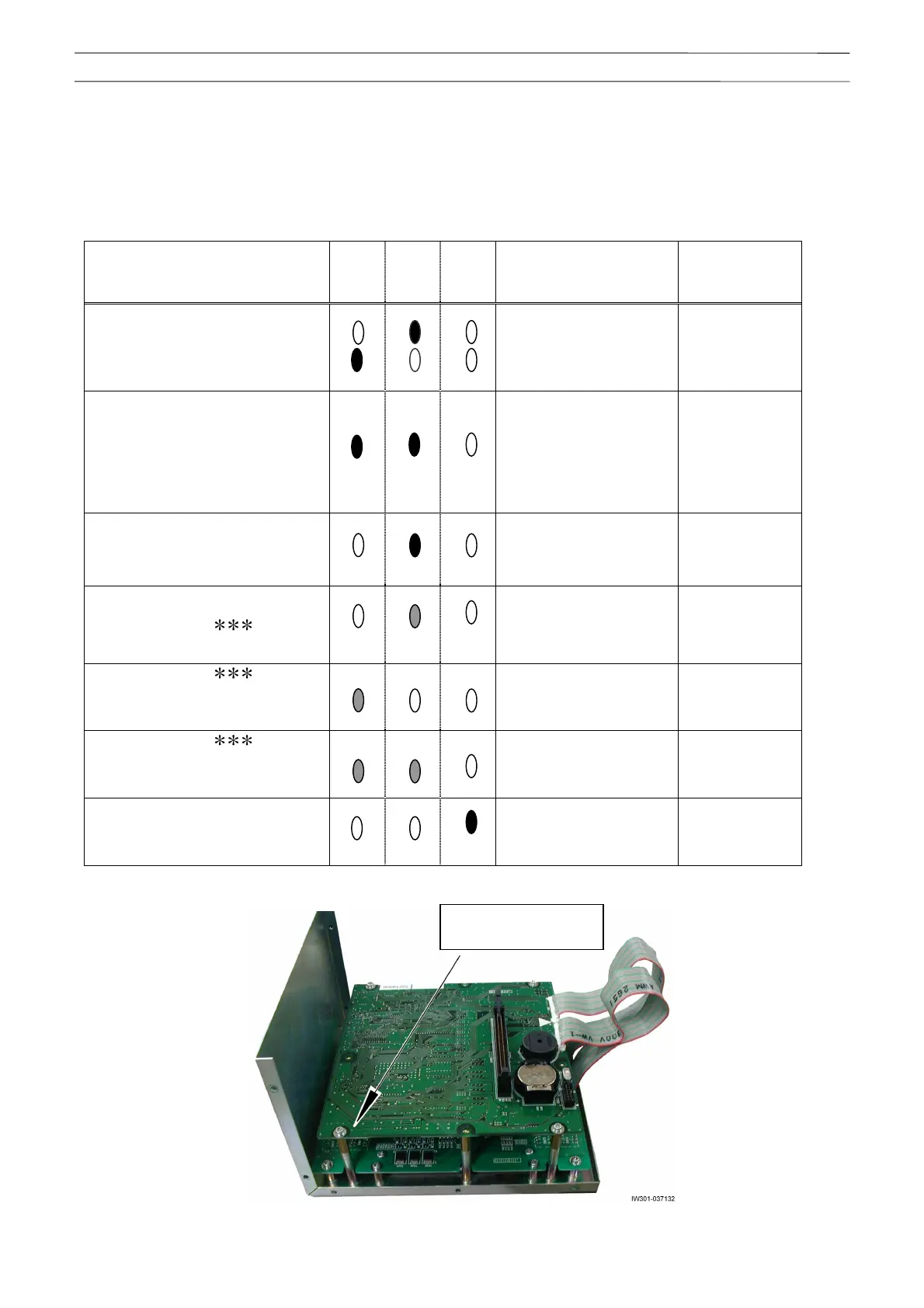
Table 4.5.1 CPU state indicator LED
CPU state LED 3 LED 2 LED 1
Description
Indication priority
(Small = High)
In normal processing LED 2 and 3 light up
alternately.
7
- In power ON initialization
processing
- Under execution of program
change
- System abnormality (CPU
exception, etc.)
LED 2 and 3 light up. 2
ROM and RAM check error LED 2 lights up. 3
Group 1 error (E1 )
LED 2 flashes. 5
Group 2 error (E2 ) LED 3 flashes. 6
Group 3 error (E3 ) LED 2 and 3 flashes. 4
In WDT operation LED 1 lights up. 1
Remove the upper case from the AML main body, and check the LED lighting status.
CPU board
(Three LEDs are mounted on
the backside.)