RUN EXCITE: Service & Maintenance Manual - rev. 1.5
TRM-25: Hand sensor board cable
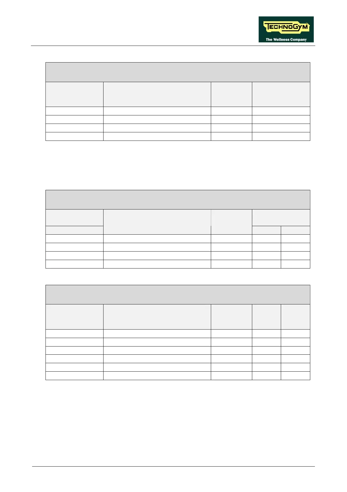
Digital Plan Board – Hand Sensor Board
Digital Plan
Board
CN13
Signal Color Hand sensor
board
J3
1 +5 Vdc power supply Brown 2
4 Board Reset Yellow -
5 Pulse out Green 3
6 Reference White 1
ATTENTION: the cable sheath contains a circuit which, in response to a reset signal received from
the Digital Plan board, is able to reset the hand sensor board by removing and subsequently re-
applying the supply voltage.
TRM-26: Sensor Cable
Hand Sensor Board - Sensors
Hand sensor
board
Sensors
J2 - J4
Signal Color
RH LH
1 Right sensor signal Yellow up -
2 Sensor signal reference White down -
4 Left sensor signal Brown - up
5 Sensor signal reference Green - down
TRM-28: OwnZone receiver cable (extension)
Digital Plan Board – Patch connectors
Digital Plan
Board
CN11
Signal Color Patch
O
Patch
N
1 Power supply White-Green 2 -
2 I2C clock Blue - 1
3 I2C data Green - 2
4 External reset Orange 3 -
7 Pulse (beat to beat) Brown 4 -
8 Gnd White-Blue 1 -
Page 2.21