STEP EXCITE: Service & maintenance manual - rev. 1.4
Page 4.8
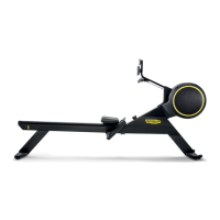
Figure 4.5-9
14. Remove cover plate f, backing off the 4
screws h using a Phillips screwdriver.
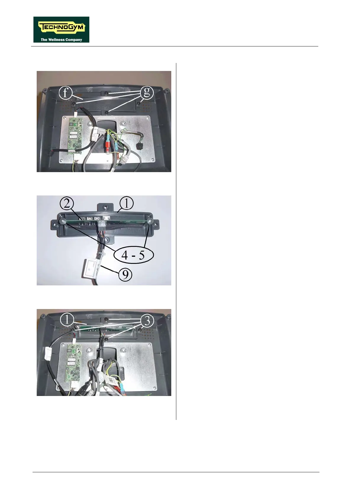
Figure 4.5-10
15. Insert external connector board 2 along the
special guides on cover plate 1, in such a
way that the connectors on the board match
up with the holes on the cover plate.
16. Secure external connector board 2 with
screws and washers 4 and 5, using a Phillips
screwdriver.
17. Connect cable 9 (CB-9) to connector board
2.
Figure 4.5-11
18. Assemble cover plate 1 inside the rear
display housing, using the 4 screws 3 and a
Phillips screwdriver.
Continued on following page →