TCP/IP dry contact device
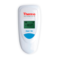
Thermo Scientific Smart-Vue
®
Wireless Monitoring Solution Administrator Guide v 2.2 87
• AC power adapter
• 1 meter (3.3 ft.) cable
• 4 international plug sizes
• 100/240 V (50/60 Hz) AC
24 V DC - 0.4 A
• RJ-45 Ethernet cable (2 meters/6.5 feet)
17.3 Smart-Vue TCP/IP
Dry Contact
specifications
• 24V - 0.4 A power adapter included
• Mounting clip
• Size: 102 x 54 x 30 mm
• Plastic enclosure: ABS (UL 94HB) RAL 9002/7032 with IP43
protection for indoor use
• Device operating conditions: 0°C to + 60°C (+32°F to +140°F)
• Electrical
• Coil power, nominal: 0.2 W
• Breaking capacity: 250 VAC /5 A
17.4 Typical installation A Smart-Vue TCP/IP Dry Contact device is connected to the network with
your Smart-Vue Server computer.
The computer running the monitoring system software triggers the dry
contact via the network when it detects an alarm condition in an
end-module or repeater.
17.5 Where to Find
More Information
The Smart-Vue Software User Manual provides detailed information on
module and system configuration. You may click on Help User manual
( ) to open the software user manual directly from within the Smart-Vue
Client software.
17.6 Installation
procedure
The procedure described here assumes that Smart-Vue Server/Smart-Vue
Client software is installed on your computer.
17.6.1 Getting started For optimal operation, follow these recommendations when placing your
device:
 Loading...