25. ROUTE SURVEYING
174
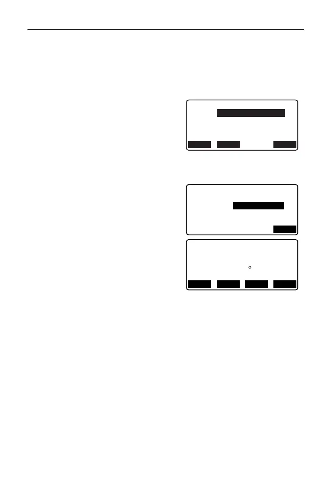
3. Input the coordinates of the KA point
(reference point). Press [OK] to set
the input values.
4. Input the coordinates of the IP point,
then press [OK].
• The azimuth angle to the IP point can
be set by pressing [AZNTH] on the
second page. Press [COORD] to
return to coordinate input.
5. Enter the curve direction, parameter
A, offset, and follow-up distance.
6. Press [OK] in the screen shown in
step 5 to calculate the center peg
coordinates. The coordinates and
azimuth are then displayed in this
screen.
7. Press {ESC} three times to finish
spiral calculation and return to
<Road>.
• Press [WIDTH] to move to the width
peg setting screen.
"25.2 Straight Line Calculation"
• The center peg can be set-out by
pressing [S-O]
"15. SETTING-OUT
MEASUREMENT"
• Curve direction: right/left
• Parameter A input range: 0.000 to 9999.999 (m)
• Station offset /Stationing chainage input range:0.000 to 99999.999 (m)
Np:
Ep:
Spiral/IP
100.000
100.000
RECLOAD OK
Spiral/CL peg
St. ofs
Sta..ing
0.000m
25.000m
Direct.
Para A
80.000m
Right
OK
N
E
120.859
Spiral/CL peg
113.755
Azmth
00 00’ 00"
WIDTH
CENTER
REC S-O