- 3 -
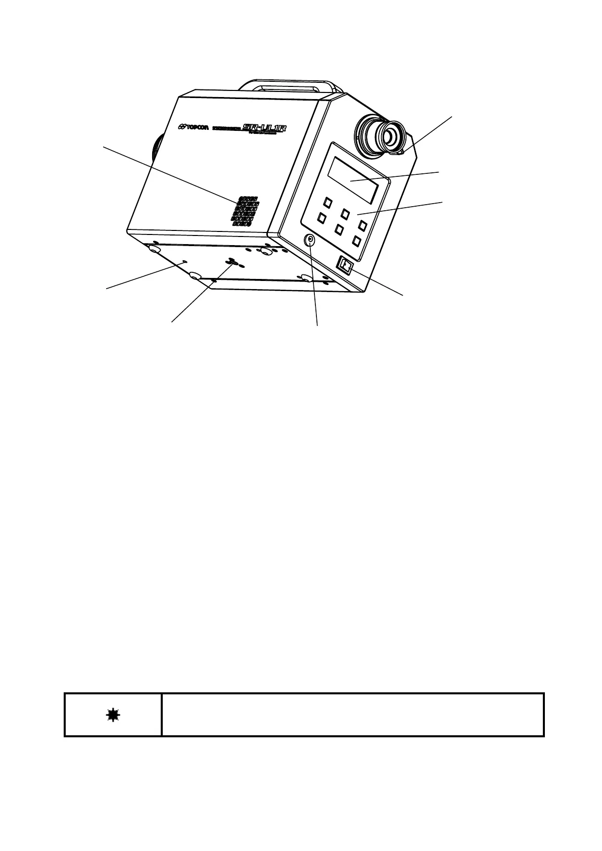
Power switch : Turns the power to the instrument on and off.
DC input connector : Connection outlet for the AC adapter.
Finder shutter selection knob
: Set the knob to "CLOSE", and the light sent through the finder can be
interrupted. When the brightness of the object is very low or when there is a
light emitting object on the finder side, set the finder shutter to "CLOSE" to
prevent light from entering through the eyepiece.
LCD screen : Displays the values, conditions and other information for measurement.
Panel switches : Includes switches to perform operations such as starting and stopping
measurements and to make the function mode settings.
Tripod screw : For attaching the SR-LEDW/SR-UL2/SR-UL1R/SR-3AR to a tripod. A 1/4-UNC
screw for mounting a camera is used.
Tool attachment screws : These are the screws for mounting the instrument. Use them when installing a
system.
The dimensions of these screws are M4 × 0.5, 3 mm in diameter with a 0.5
mm pitch.
☞
‘6 Appendix: External Dimension Diagram’
Use only specified screws when using the tripod screw and screw holes for jig
attachment. Do not tighten the screws any more than necessary. Doing so might
cause internal breakage.