11. HOW TO ADJUST THE PRINT HEAD POSITION EO18-33027
(Revision Date: Jun., 2017)
11.2 PRINT HEAD POSITION ADJUSTMENT PROCEDURE
11- 2
6) Place the removed print head ass’y on an antistatic sheet. Remove “Loctite” applied to the print head
fixing screws and loosen the screws.
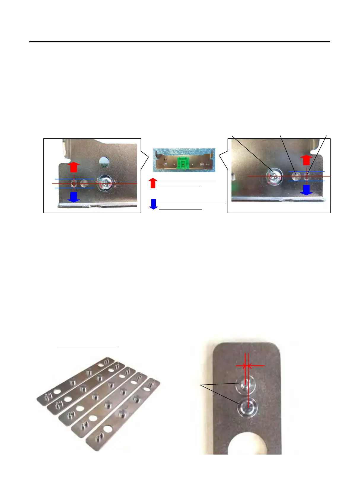
First, align the center of the print head fixing screws, the positioning holes, and the adjustment holes,
then perform a print test.
If blurred print occurs, move the print head forward (in the positive direction) and repeat the print test
until the print quality becomes proper.
If smudge occurs, move the print head backward (in the negative direction) and repeat the print test
until the print quality becomes proper.
It is recommended to make adjustment in units of 0.1mm and move both sides at the same time.
7) When the best position is determined, tighten the print head fixing screws.
The above-mentioned procedures are the basic of print head position adjustment for TTEC barcode printers.
11.2.1 Print head position adjustment using adjustment jigs
These jigs are used when replacing the print head to adjust the position of a newly installed print head in
the same way as the original one. The jigs also help you secure proper print quality with user’s media and
ribbon.
There are 5 types of jigs (±0.0mm jig, ±0.1mm jig, ±0.2mm jig, ±0.3mm jig, and ±0.4mm jig), which enables
an adjustment in the range up to ±0.4mm, in units of 0.1mm.
Please be careful of the numbers and “+” and “-” symbols marked on the jigs.
Positive direction or negative direction is selected by changing the fitting direction of the jig.
Up to 0.4mm in - (negative)
direction (backward)
Up to 0.4mm in + (positive)
direction (forward)
Positioning hole
Adjustment hole
Print head fixing screw
Positioning stud
0.1mm to 0.4mm
(The distance is different
depending on the jig)
B-EX Head Ad
ust Ji

 Loading...