4. INSTALLATION PROCEDURE FOR OPTIONAL EQUIPMENT EO18-33027
(Revised: FEB., 2020)
4.9 SERIAL INTERFACE BOARD (B-EX700-RS-QM-R)
4-45
4.9 SERIAL INTERFACE BOARD (B-EX700-RS-QM-R)
The following parts are supplied with the kit. Make sure you have all items shown below.
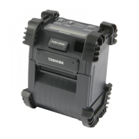
Serial Interface Board (1 pc.)
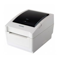
M-3x6 Screw (2 pcs.)
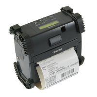
Installation Manual (1 copy)
NOTE: This module cannot be used together with the B-EX700-WLAN-QM-R wireless LAN board.
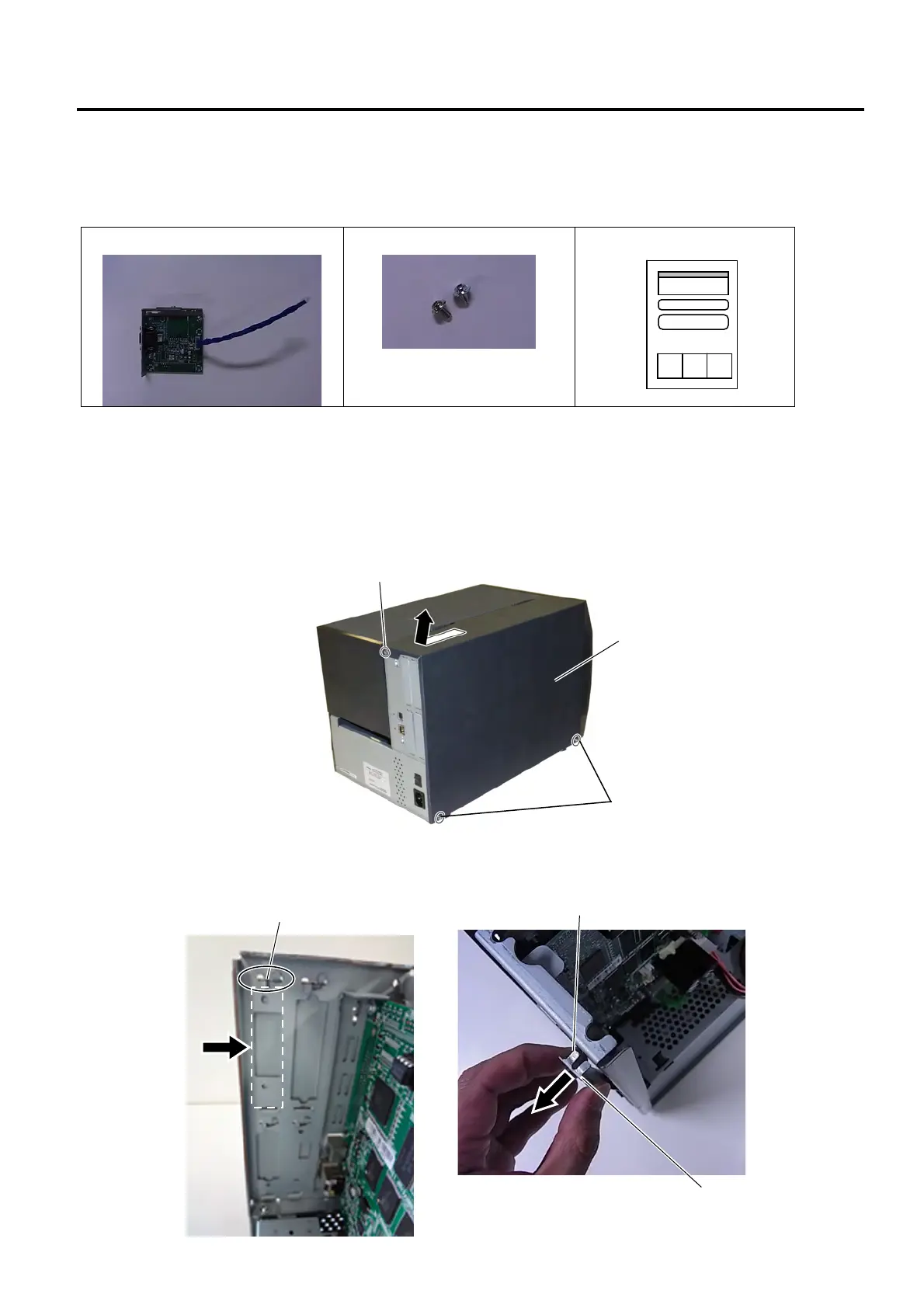
1. Turn the printer power off and disconnect the Power Cord.
2. Remove the three B-4x5 screws from the Side Panel (L).
3. Slide the Side Panel (L) backward, and raise it to remove from the printer.
4. Unfold the upper and lower tabs of the Blind Plate indicated by the arrow, then pull and remove the
Blind Plate from the printer back.
B-4x5 Screw
Side Panel (L)
B-4x5 Screw
Blind Plate
Tab
Tab

 Loading...