4. INSTALLATION PROCEDURE FOR OPTIONAL EQUIPMENT EO18-33027
(Revision Date: Aug. 24, 2011)
4.11 HF RFID MODULE MOUNT KIT (B-EX700-RFID-H1-QM-R)
4-72
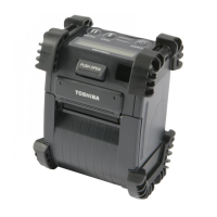
All the following parts are supplied with the kit. Make sure you have all items shown below.
RFID Plate (1 pc.)
Antenna Frame (1 pc.) Ribbon Guide (1 pc.)
Module Attachment Plate
(2 pcs.)
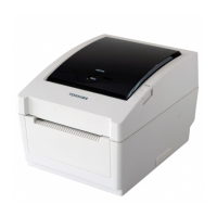
Earth Plate (1 pc.) Bush (1 pc.) Interface Cable (1 pc.) SMW-3x6 Double Sems
Screw (1 pc.)
PT-3x6 P-TITE Screw
(5 pcs.)
Spacer (Short) (2 pcs.) Nylon Washer (2 pcs.) SMW-2x10 Double Sems
Screw (2 pcs.)
SMW-3x25 Double Sems
Screw (2 pcs.)
Spacer (Long) (2 pcs.)
Cable Clamp (1 pc.)
(Not used)
Installation Manual
(1 copy)
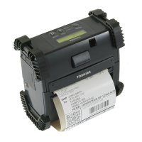
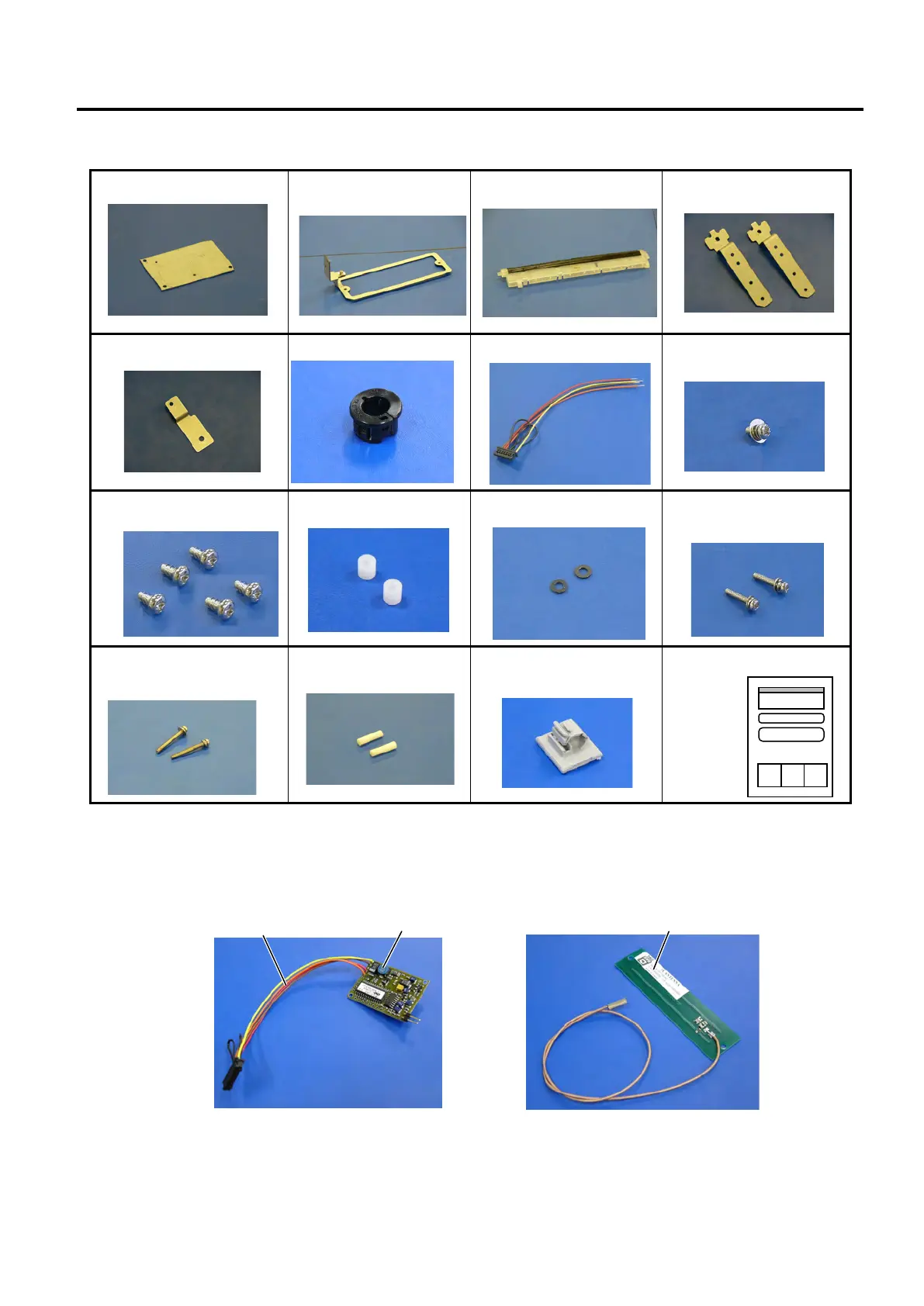
NOTE:
To install the B-EX700-RFID-H1-QM-R in the printer, TAGSYS RFID Module MEDIO
TM
S002 and the exclusive
antenna are required separately. Before installation, solder the supplied Interface Cable to the RFID module as
shown in the picture below, and attach the RFID Module and the Antenna to the RFID Plate and the Antenna
Frame, respectively.

 Loading...