iSTAR eX Diagnostic Tests
iSTAR eX Installation and Configuration Guide 7–5
You can also use the iSTAR Web Page Diagnostic Utility to view reader
diagnostic information. For information about this utility, see “Diagnostic
Screens” on page 6-10.
Output Diagnostics
The iSTAR eX provides three types of output tests:
Output Change Display (slow) – tests a specific output that is activated
manually by the technician
Output Change Display (fast) – activates and tests every output on the
system. (Onboard outputs, reader outputs and R/8 outputs)
Output Test Mode – activates and tests onboard outputs one by one.
Output Change Display (Slow Mode)
The manual output test is an end-to-end test that displays information about
outputs activated manually by a technician. The outputs you are testing can
be attached to iSTAR eX through readers and R/8 boards. Information
displays on the LED for two seconds.
To activate the output change display test, set rotary switch SW1 to the
position shown in Table 7.3.
Output Change Display (Fast Mode)
The output change display test is an end-to-end test that automatically
activates all outputs attached to iSTAR eX. The outputs you are testing can be
attached to iSTAR eX through readers and R/8 boards. Output information
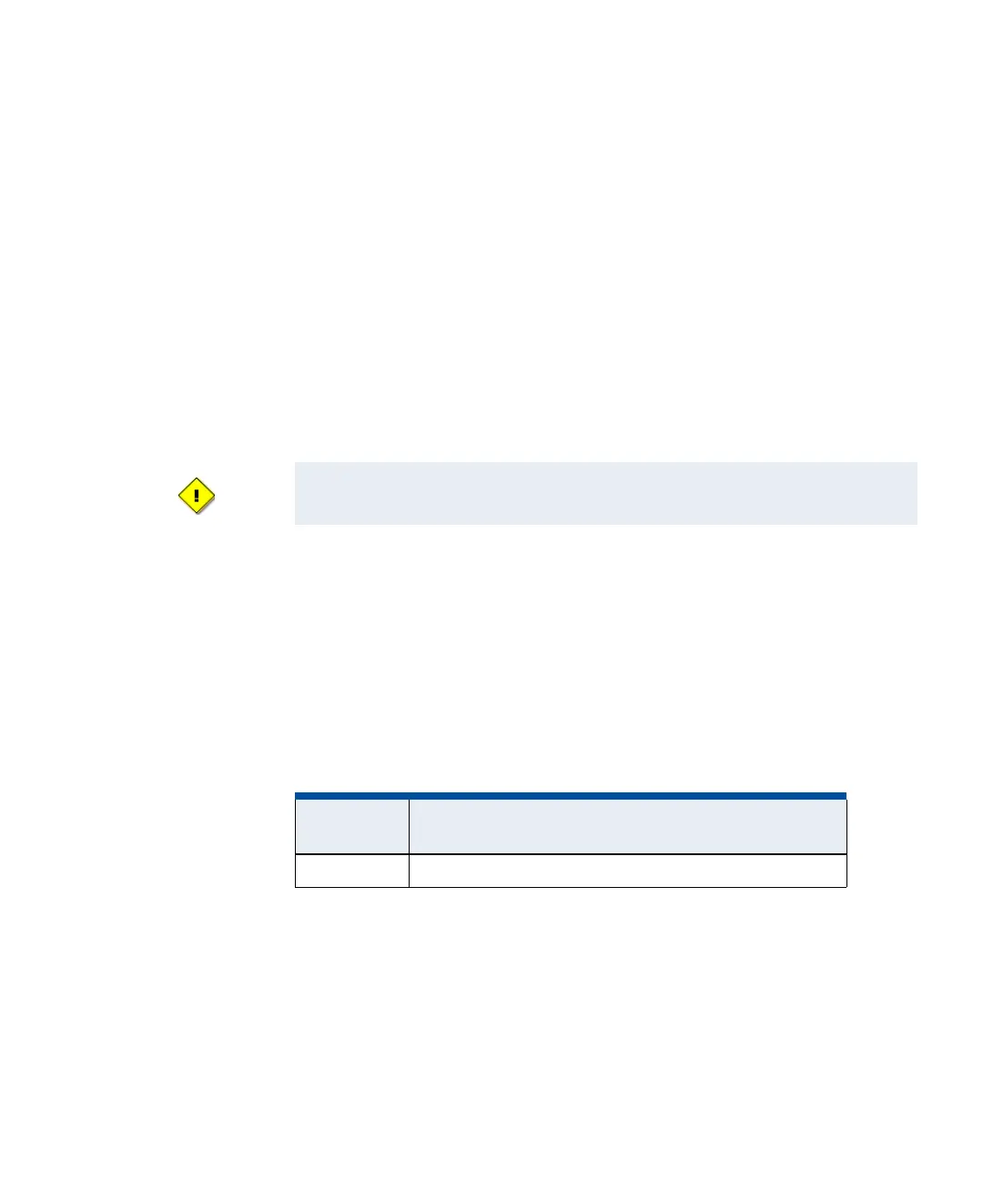
Do not activate outputs on a live system!
Table 7.3: Manual Output Test Switch Settings
Switch
Position Function
SW1-5 Activate output change display for two seconds (slow mode)