A–2 iSTAR eX Installation and Configuration Guide
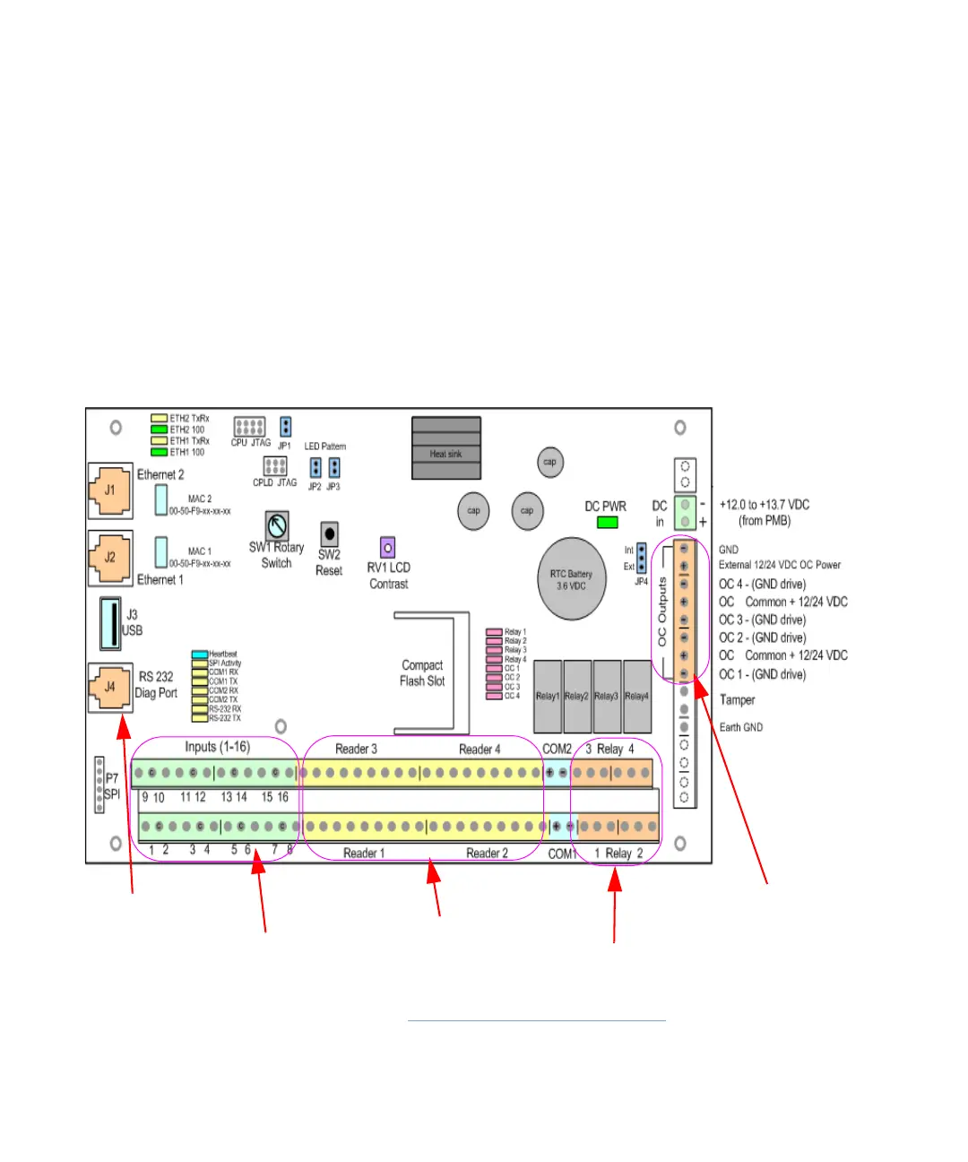
iSTAR eX GCM Controls and Indicators
The iSTAR eX GCM contains the following switches and reset buttons for use
during hardware setup and configuration.
SW1 Rotary Switch - Block ICU, Reset Memory, Run Diagnostics
SW2 Reset button – reboots the iSTAR eX
LED indicators – indicate Ethernet links, COM ports, Output status.
RV1 LCD Contrast – controls the contrast level on the LCD.
Figure A.1 shows the location of the controls and indicators.
Figure A.1: iSTAR eX GCM Controls and LEDs
16 General Purpose Inputs
4 Direct Wiegand Reader Ports
4 Relay Outputs
4 Open Collector Outputs
Diagnostic Cable Port