PMB Controls and Indicators
iSTAR eX Installation and Configuration Guide A–9
3 Wire (Red, Green, Yellow)
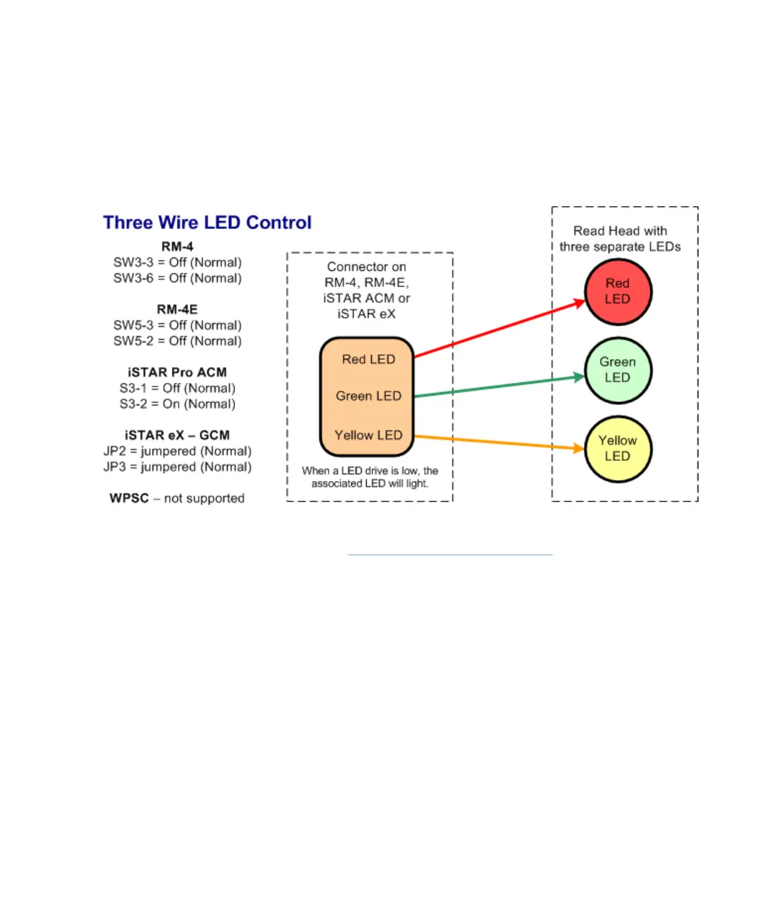
When JP2 and JP3 are jumpered, it specifies Three wire LED control. In this
case, the Red, Green, and Yellow LED drives are wired to the associated LED
of the same color as shown in Figure A.5.
Figure A.5: Three wire LED control
When JP3 is not jumpered, it specifies One Wire (A,B,C) mode. In this case, a
single LED drive (Red or Green or Yellow) is wired with varying results as
shown in Figure A.6.
Three Wire LED Control mode is typically used for older read heads that have
a single LED that is either On, Off, or flashing.