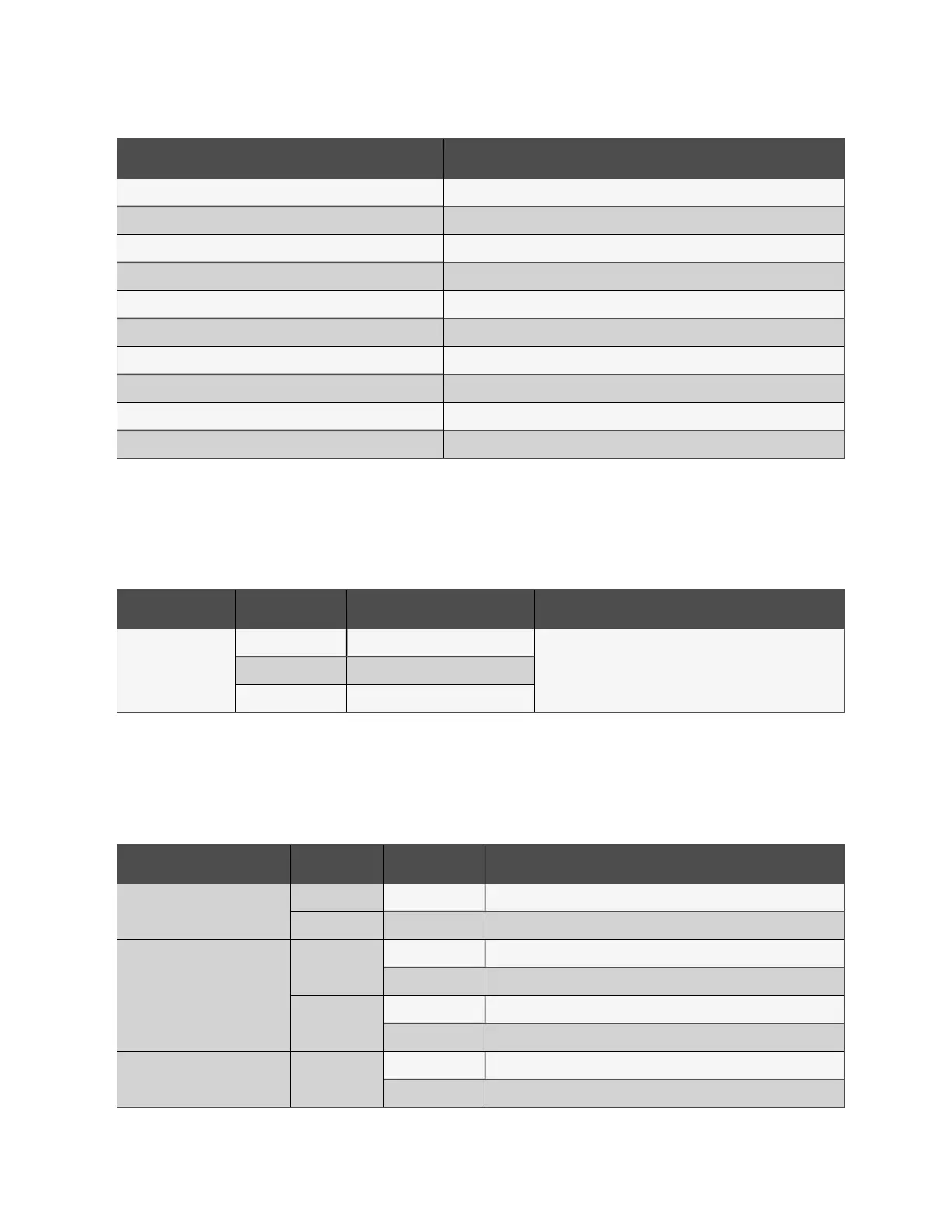
Number Description
1 Power input 1
2 Power indicator
3 Power input 2
4 Reset button
5 Optical fiber indicator
6 Optical SFP
7 Display Port (DP)
8 HDMI port
9 Ethernet (LAN) ports
10 USBports
Table 2.15 Monitoring Unit Rear Panel Description
Power input
The rear panel of the monitoring unit has two isolated power inputs as shown in Monitoring Unit Rear Panel on the previous
page . The following table describes the power input parameters.
Power Input Range Interface
ACinput
Voltage 63.6 VDC to 152.64 VDC
C14 inlet with power cord retention featureCurrent <2A
Frequency 50/60Hz
Table 2.16 Power Input Parameters
Indicators
The front panel of the monitoring unit has three indicators as shown in Monitoring Unit Front Panel on the previous page . The
following table provides descriptions for the front panel indicators.
Silk Screen Printing Color Status Description
Run/Alarm
Green On No alarm
Red On Alarm
COM/Sensor
Green
Blink Receiving data
Off No data received
Yellow
Blink Transmitting data
Off No data transmitted
DI/A/DO/AO/Smoke Green
On External device is connected
Off No external device is connected or the port is short circuited
Table 2.17 Monitoring Unit Front Panel Indicator Description
2 Getting Started Proprietary and Confidential ©2024 Vertiv Group Corp. 15
Vertiv™ SmartRow™ 2 Infrastructure Solution User Guide