Number
Touch
Key
Functional Description
12 Unit address Show unit address.
13 Time display Show current time and date.
14 Graph button
Show the graphs of average return air temperature, average return air humidity, average supply air temperature, and
average remote temperature.
15 Setting button Set the temperature and humidity.
Table 7.7 CRD10 Display Screen (continued)
To configure the cooling unit:
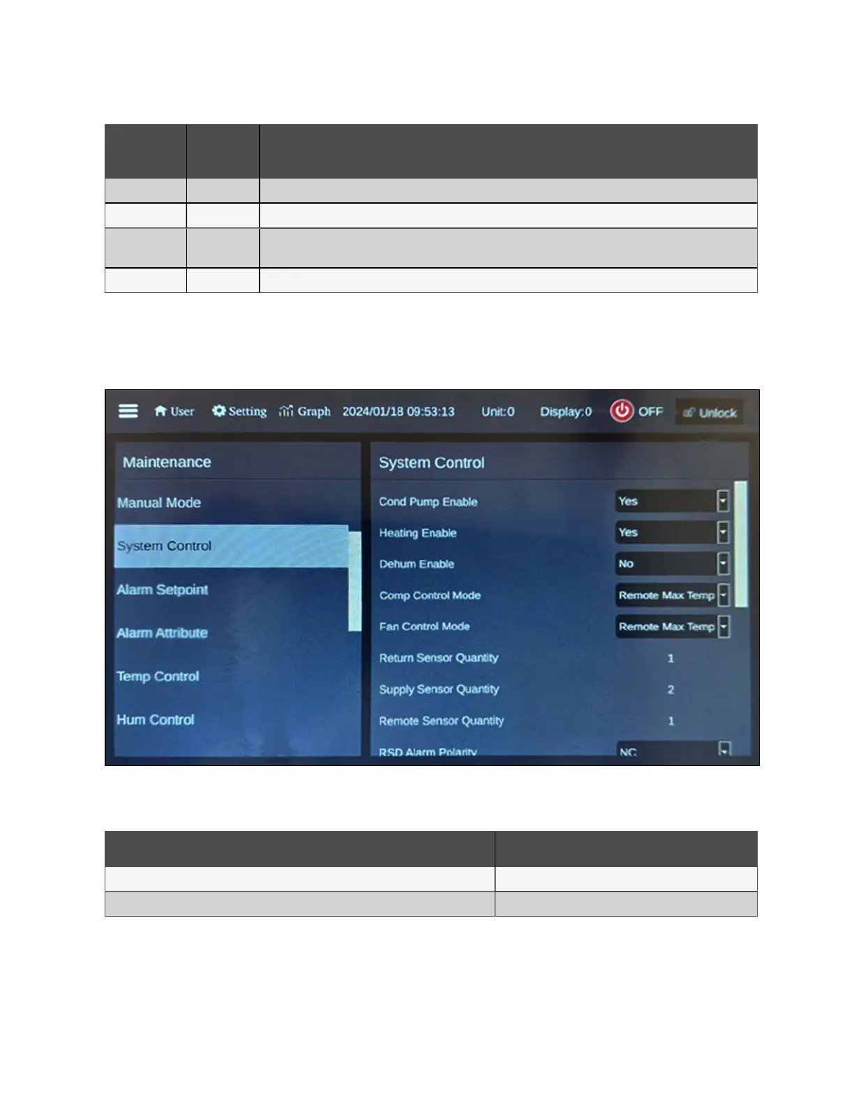
1. From the HMI display, press Setting. The following screen appears.
Figure 7.19 CRD10 System Control Screen
2. Configure the temperature settings as described in the table below.
Setting Configuration
Temp Setting/Supply AVG Temp SP 68 °F (20 °C)
Temp Setting/Remote AVG Temp SP 71.6 °F (22 °C)
Table 7.8 CRD10 System Control Configurations
NOTE: The Remote AVG TempSet Point should be 1-2 K higher than the Supply AVG TempSet Point.
NOTE: Both temperature set points can also be modified via the main HMI display located on the PMC. For more
information, please refer to Thermal on page73 .
7 Network Settings Proprietary and Confidential ©2024 Vertiv Group Corp. 65
Vertiv™ SmartRow™ 2 Infrastructure Solution User Guide