Personal TitleMaker User Guide
144
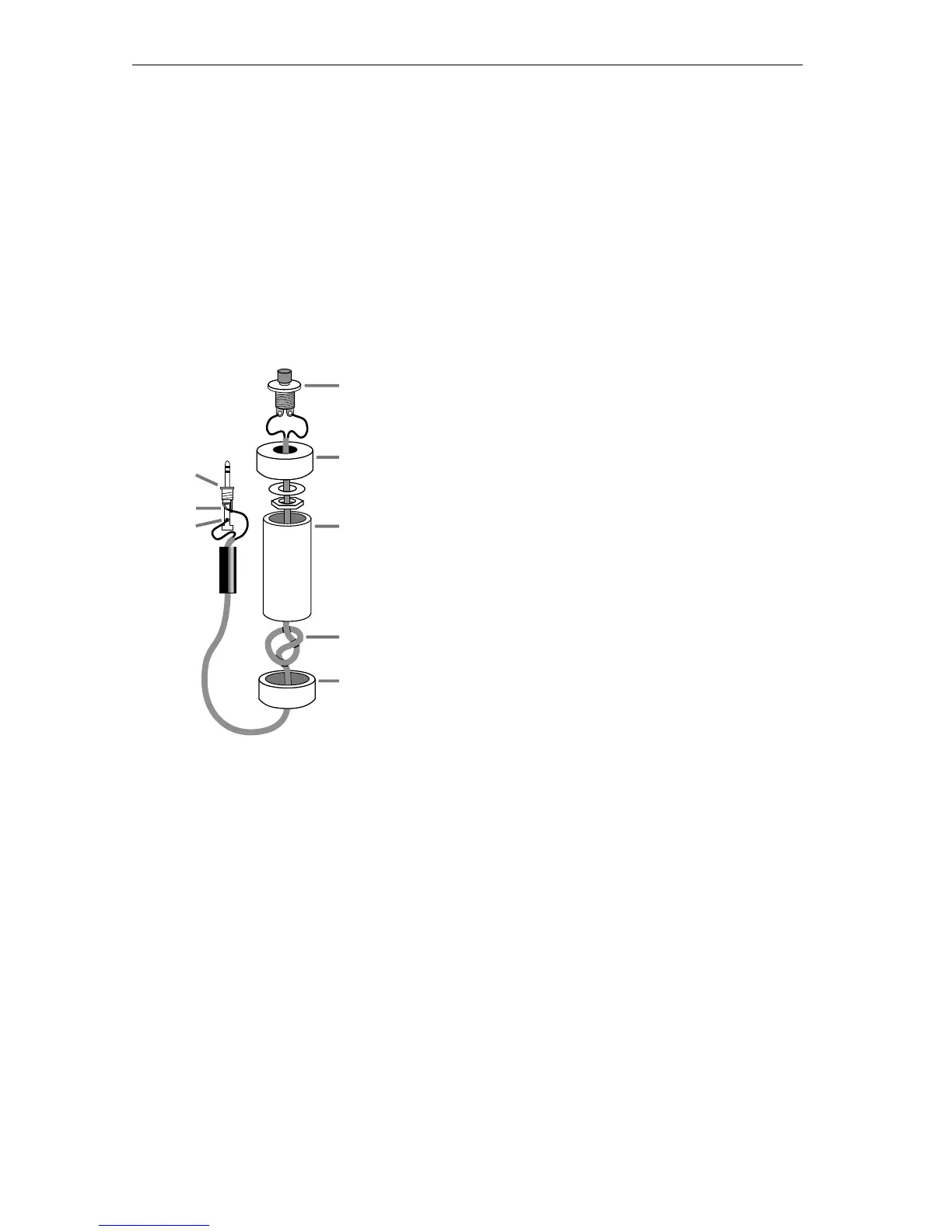
INSTRUCTIONS FOR BUILDING A GPI TRIGGER
This section contains a diagram of the GPI Trigger Button you can build
and all associated instructions.
Tools Required
A soldering iron and solder
Wire cutters
An electric drill
Parts Required
One four-inch piece of 3/4-inch PVC pipe (
C)
and two end caps (
B and E).
3-conductor, 22-24 gauge stranded wire cable
(
D).
A “normally open momentary push-button
switch” (
A).
A stereo 3.5-mm mini-pin plug (
F)
Instructions:
1 Drill a 1/4-inch hole in the center of one PVC end cap (E) and
a hole to match the push-button switch in the other end cap
(
B).
2 Feed one end of the cable through the end cap with the 1/4-
inch hole (
E) and strip the end of each wire.
3 Tie a single knot (
D) about 8 inches from the end of the wire.
4 Slide the wire through the PVC pipe, the nut and washer, and
the other end cap (B).
5 Solder the two wires at the knotted end to the two poles on
the switch (
A).
F
A
C
D
G
H
B
E