Installation and initial operation 72800115 Markoprint X4JET
Seite 63 von 177 GB
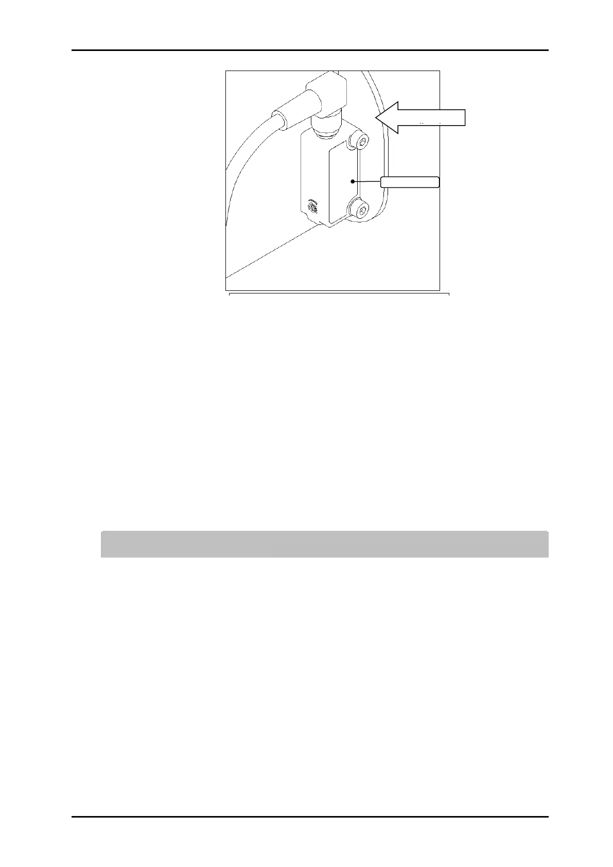
Fig. 30: Photo sensor installation
5. Connect the light barrier cable to the connector of the photo sensor and tighten.
6. Using the two screws supplied, mount the light barrier to the print head (Fig. 25) in such a
way that the product to be printed passes the light barrier before passing the print head.
The photo cell should have an unlimited view to the product (send- and reception diode).
Tighten the screws only to the extent that the plastic enclosure will not be damaged.
Alternatively, another sensor may be used.
Observe the direction of movement of the conveyor belt!
7. Mount optional rotary encoder on production line.
8. Connect the rotary encoder cable to the rotary encoder connector and fasten.
9. If necessary, mount an additional screen to protect the print head.
10. Check data of the public power supply with the technical data of the power supply.
Chapter 0, Page 19 Take the electrical connection by correlation only!
11. Remove the protective foil from the nozzle plate and insert the ink cartridge in the holder.
Chapter Insert / remove LX ink cartridge, Page 64
To avoid faults caused by potential differences, the controller must be electrically
connected to the conveyor belt.
12. When laying the cables, ensure that cables are not tripping hazards and do not lay them
around corners and sharp edges. Avoid abrasive surfaces.