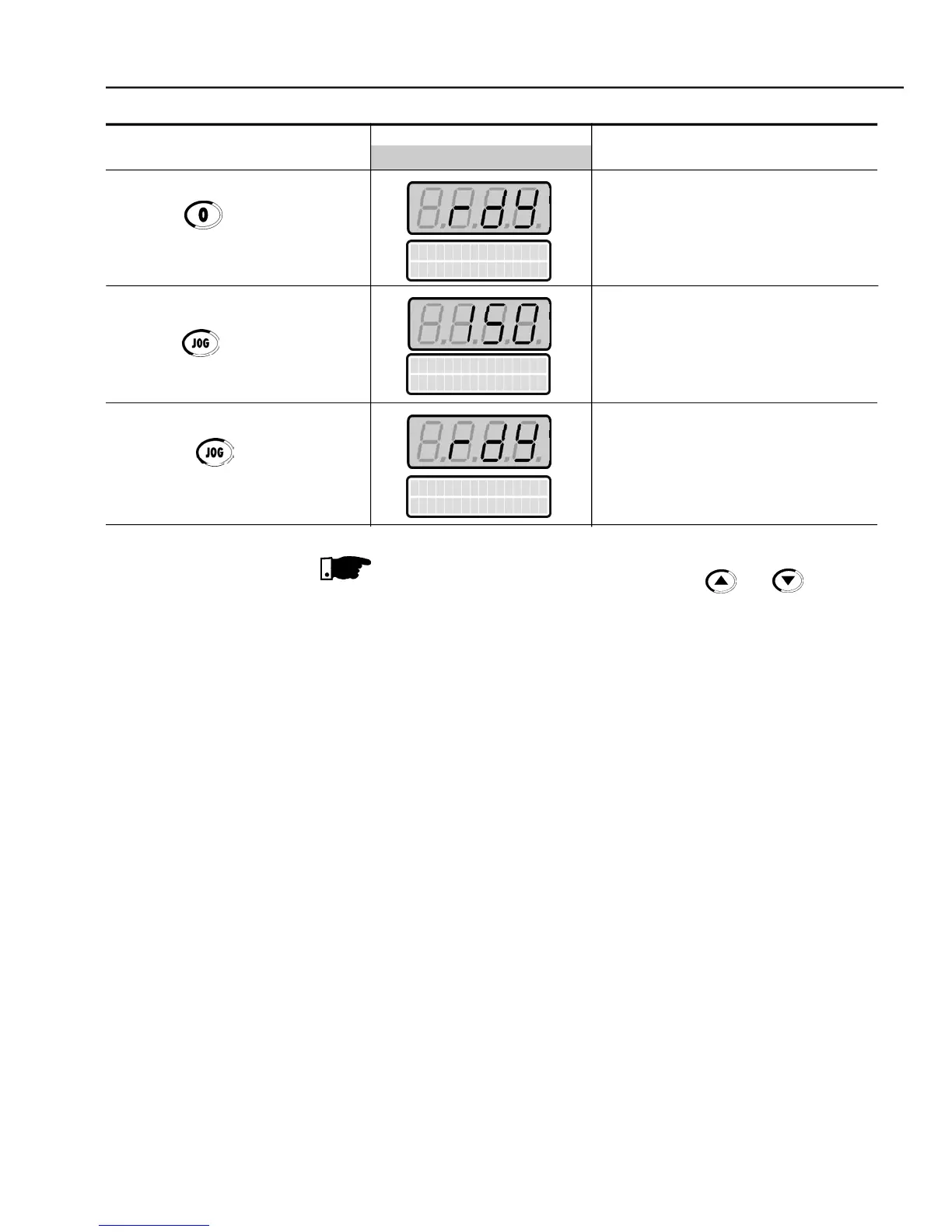
Press the key and hold it
Motor decelerates down to 0 rpm
Motor accelerates from 0 rpm up to
the JOG speed set at P122
CCW direction of rotation
Motor decelerates down to 0 rpm
The last frequency reference value set via the and keys is saved.
If youwishto changethis value beforeenablingtheinverter, change parameter
If the rotation direction of the motor is not correct, switch off the inverter.
Wait 10 minutes to allow a complete discharge of the capacitors and then
swap any two wires at the motor output.
If the acceleration current becomes too high, specially at low frequencies
(< 15 Hz), adjust the Torque Boost at
Increase/decrease the content of
graduallyuntil you obtain an
operation with constant current over the entire frequencyrange.
Refer to P136 in chapter 6.
If E01 fault occurs during deceleration, increase the deceleration time at