Opentheinput circuitbreakerordisconnectswitchtoshut down theCFW-09.
To repeat the initial power-up procedure:
(this loads the factory default parameters)
and follow the initialpower-up sub-routine again;
The initial power-up sub-routine described above automatically sets some
parameters according to theentered data. For moredetails, refer to chapter 6.
Modification of motor characteristics after the first power up:
Insert the motor data at parameters P400 to P407;
For operation in the vector mode run the self-tuning routine (P408 > 0);
Set P156, P157, P158, P169, P170, P171, and P172;
Power the inverter down and up for the new settings to take place and for
the proper motor operation.
Modification of motor characteristics after the first power up, for operation in
Follow the previous procedures and also set parameter P297 to 2.5 kHz.
describes thestart-upprocedure when operating via the Keypad (HMI).
Four types of control will be considered:
V/F 60 Hz, Sensorless Vector, Vector
with Encoder Feedback and VVW (Voltage Vector
Even after the AC input is disconnected, high voltages may still be present.
Wait at least 10 minutes after powering down to allow a full discharge of the
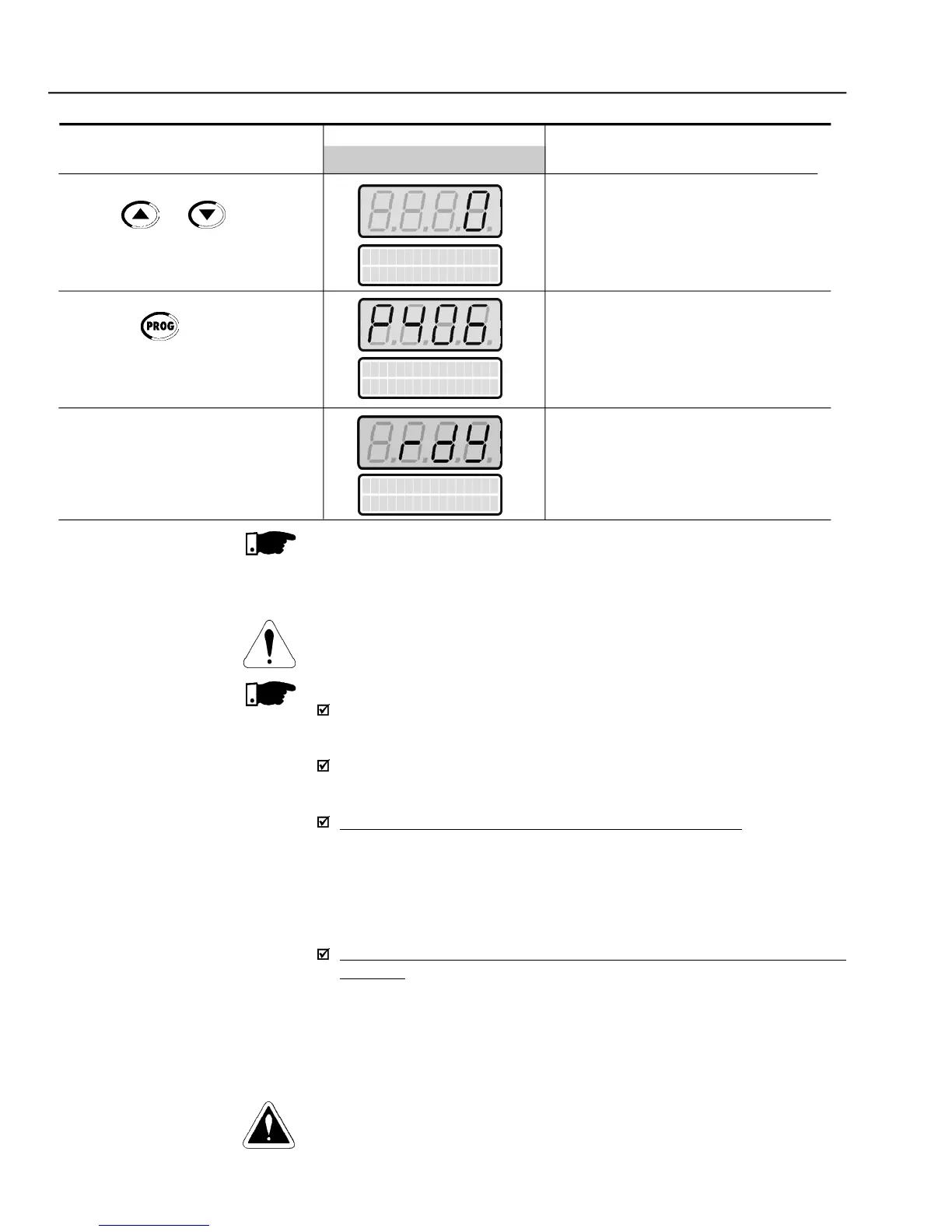
Selected Motor Ventilation Type:
Exit the programming mode
The first power-up routine is finished.
Inverter is readyto operate
Use the and keys to select
the motor ventilation type
Press the key to save the
selected option and exit the
P401 maximum value is 1.8 x P295 for model 4.2 A/500-600 V and 1.6 x
P295 for models 7Aand 54A/220-230 V; 2.9Aand
and 247 A/500-690 V; 100 A, 127A and 340 A/660-690 V.