CHAPTER 8 - CFW-09 OPTIONS AND ACCESSORIES
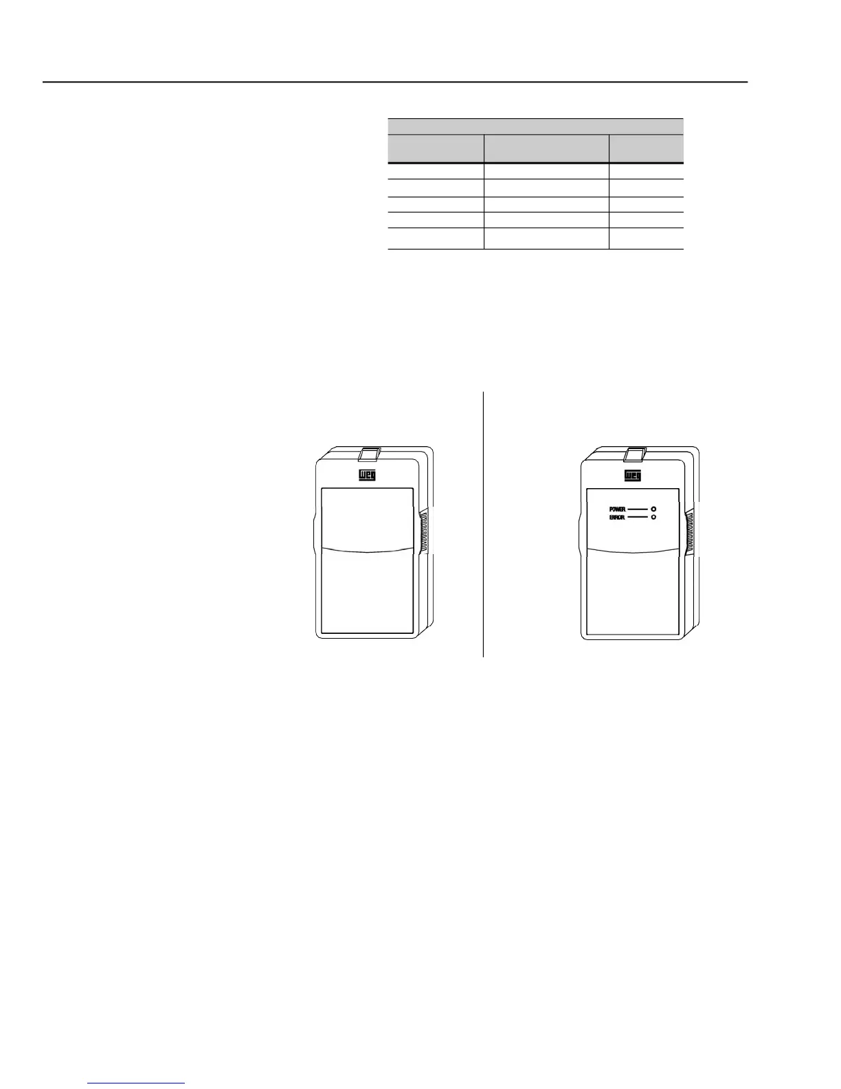
b) CFW-09 Blank Cover with Power
(to be mounted in the inverter)
The CFW-09 can be controlled, programmed and monitored via an RS-232
Serial Interface. The communication protocol is based on question/response
telegramsaccordingtoISO1745andISO 646standards,withASCII characters
exchanged between the inverter and a master (network controller, which can
be a PLC, PC, etc.). The maximum transfer rate is 9600 bps. The RS-232
serialinterface is not galvanically isolated from the 0 V reference of the inver-
ter electronics, therefore the maximum recommended serial cable length is
To implement the serial communication, an RS-232 SERIAL INTERFACE
module has to be added to the CFW-09. This module is installed in place of
the Keypad, making the RS-232 connection (RJ11 connector) available. If the
useof the HMI is alsorequired, the RS-232modulealso providesits connection.
(to be mounted in the frame)
As shown in figure 8.17, two types of blank covers are available to be used, in
the inverter or in the frame, when the keypad is not in place.