CHAPTER 6 - DETAILED PARAMETER DESCRIPTION
Optimal braking is active as described in P151 for vector
control. This gives the shortest possible deceleration time
without using dynamic braking or regeneration.
Automatic deceleration ramp control. Optimal braking is not
active. The deceleration ramp is automatically adjusted to
keep the DC link voltage below the level set in P151. This
avoids E01 DC link overvoltage tripping. Can also be used
The Braking acts as described for 150 = 0;
The WithoutLosses braking becomes inactive.
The DC link voltage will be controlled by parameter
DC Link voltage regulation mode
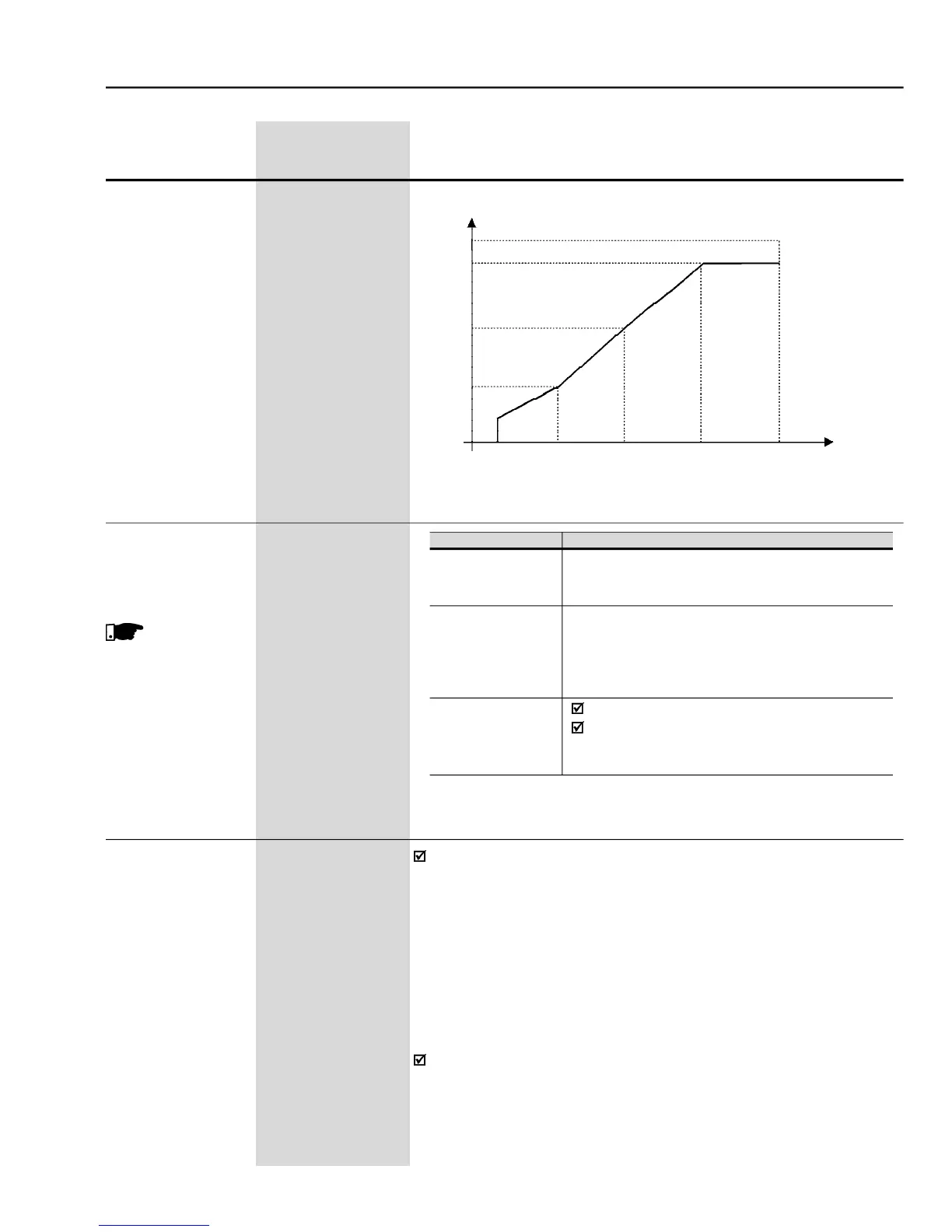
P151 sets the DC Link Voltage Regulation Level to prevent E01-
overvoltage. This Parameter jointlywiththe Parameter P152 allows two
operation modes for the DC Link Voltage Regulation. Please findbelow
a description of the two operation modes.
DC Link Voltage Regulation type when P152 = 0.00 and P151 is
different from the maximum value:
ramp Holding – When the DC
Link Voltage reaches the Regulation Level during the deceleration, the
deceleration ramp time is increased and the speed is maintained at a
constant value till the DC Link Voltage leaves the actuation. Refer to
This DC Link Voltage Regulation (rampholding) triestoavoid the inverter
disabling through fault relating to DC Link Overvoltage(E01), when the
deceleration of loads with highinertia is carried out, or decelerationwith
short times are performed.
- Adjustable V/F curve V/F


 To Next Page