CHAPTER 8 - CFW-09 OPTIONS AND ACCESSORIES
The inverter that is fitted with the Profibus DP Kit operates in slave mode,
allowing the reading/writing of their parameters through a master. The inverter
does not start the communication with other nodes, it only answers to the
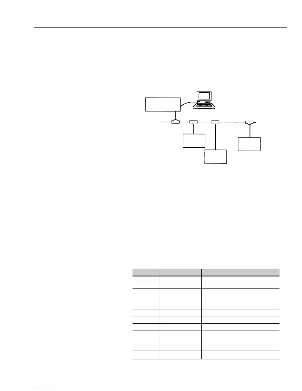
master controls. Atwisted pair of copper cable realizes the connection of the
Fieldbus (RS-485) allowing the data transmission at rates between 9.6 kbits/s
and 12 Mbits/s. Figure 8.39 show a general view of a Profibus DP network.
- Fieldbus Type: PROFIBUS DP EN 50170 (DIN 19245)
Transmission means: Profibus bus bar line, type A or B as specified in
Topology: Master-Slave communication.
Insulation: the bus is supplied by DC/DC inverter and isolated galvanically
from remaining electronics and the signals A and B are isolated by means
It allows the connection/disconnection of only one node without affecting
Fieldbus connector of the inverter user
- Connector D-sub 9 pins - female.
RxD/TxD positive, according to
0 V isolated against RS-485 circuit
5 V isolated against RS-485 circuit
RxD/TxD negative, according to
Connectedto the groundprotection (PE)
- Pin connection (DB9) to the Profibus DP